
OLED luminous layer structure capable of avoiding color cast and coupled film of OLED luminous layer structure

A technology of light-emitting layer and coupling film, applied in the manufacturing of electrical components, electric solid-state devices, semiconductor/solid-state devices, etc., can solve problems such as uneven distribution, loss of light intensity, color shift of mobile phone screens, etc., to improve optical quality, eliminate color cast effect

Active Publication Date: 2014-04-16
EVERDISPLAY OPTRONICS (SHANGHAI) CO LTD
View PDF5 Cites 4 Cited by
  • Summary
  • Abstract
  • Description
  • Claims
  • Application Information

AI Technical Summary

Problems solved by technology

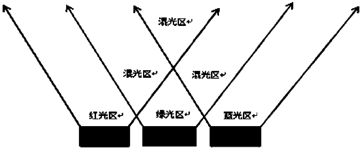
[0002] In terms of color control, OLED does not require a backlight source, so it is enough to only control the color of the color filter (Color filter, referred to as CF) layer, and the current CF production technology for OLED directly uses RGB organic materials, but due to The organic material itself will lose the light intensity, coupled with the change of the supply flow of the device itself, the energy emitted by the R, G, and B three-color lights will be unevenly distributed in certain directions (compared to the proportional mixing), resulting in mobile phone screen There will be serious color shift

Method used


Image

  • OLED luminous layer structure capable of avoiding color cast and coupled film of OLED luminous layer structure
  • OLED luminous layer structure capable of avoiding color cast and coupled film of OLED luminous layer structure
  • OLED luminous layer structure capable of avoiding color cast and coupled film of OLED luminous layer structure

Examples


Embodiment Construction

[0015] The present invention will be further described in detail below in conjunction with the accompanying drawings and specific embodiments.

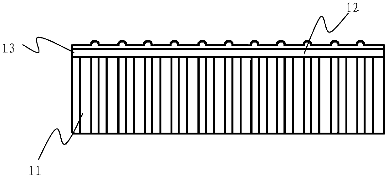
[0016] see first figure 2 As shown, the present invention discloses an OLED light-emitting layer structure that can avoid color shift, including an OLED light-emitting layer 11 and a polarizer 13 arranged on the OLED light-emitting layer 11, and the OLED light-emitting layer 11 further includes sequentially arranged Red, green, and blue three-color blocks, wherein, a coupling film 12 is further provided on the polarizer 12, combined with image 3 As shown, the coupling film 12 includes a bottom film 121 and gate-shaped protrusions 122 attached on the bottom film 121 . The grid-shaped protrusions 122 correspond to the color gamut where color shift occurs in the red, green, and blue color blocks of the OLED light emitting layer 11 . The grid-shaped protrusions 122 on the coupling film 12 increase or decrease the amount of light outpu...


PUM

PropertyMeasurementUnit
Diameteraaaaaaaaaa

Abstract

The invention discloses an OLED luminous layer structure capable of avoiding color cast and a coupled film of the OLED luminous layer structure. The OLED luminous layer structure capable of avoiding the color cast comprises an OLED luminous layer and a polarizer arranged on the OLED luminous layer, wherein the OLED luminous layer further comprises a red color block, a green color block and a blue color block which are arranged in sequence, the coupled film is arranged on the polarizer, and grid type protrusions are arranged at the portions, corresponding to color areas where the color cast is generated in the red color block, the green color block and the blue color block, of the coupled film. The coupled film is added on the polarizer, an oval grid type protrusion structure arranged on the coupled film is utilized, light getting out quantity in a certain direction is added or reduced oriented to the color areas where the color cast is generated in the red color block, the green color block and the blue color block and which correspond to the oval grid type protrusion structure, in this way, the purpose of regulating hue energy is achieved, R color energy, G color energy and B color energy are gathered and blended proportionally in the certain direction, white light without the color cast is obtained, the color cast of a display screen is eliminated, and the overall optical quality of a mobile phone panel is improved.

Description

technical field [0001] The invention relates to a manufacturing process of an optical element, in particular to an OLED light-emitting layer structure capable of avoiding color shift and a coupling film thereof. Background technique [0002] In terms of color control, OLED does not require a backlight source, so it is enough to only control the color of the color filter (Color filter, referred to as CF) layer, and the current CF production technology for OLED directly uses RGB organic materials, but due to The organic material itself will lose the light intensity, coupled with the change of the supply flow of the device itself, the energy emitted by the R, G, and B three-color lights will be unevenly distributed in certain directions (compared to the proportional mixing), resulting in mobile phone screen There will be serious color shift. [0003] refer to figure 1 As shown, when the light of the three colors of R, G, and B enters the light-emitting layer, we divide the wh...

Claims


Application Information

Patent Timeline
IPC IPC(8): H01L51/50H01L51/52
CPCH10K59/35H10K50/85
Inventor 未治奎
Owner EVERDISPLAY OPTRONICS (SHANGHAI) CO LTD
Learn More