A seawater flake ice machine evaporator
A flake ice machine and evaporator technology, used in evaporator/condenser, ice making, ice making, etc., can solve problems such as the shape of vulnerable aquatic products, death, and the increased fuel consumption of sailing with ice cubes on board
- Summary
- Abstract
- Description
- Claims
- Application Information
AI Technical Summary
Problems solved by technology
Method used
Image
Examples
Embodiment 1
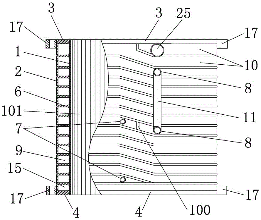
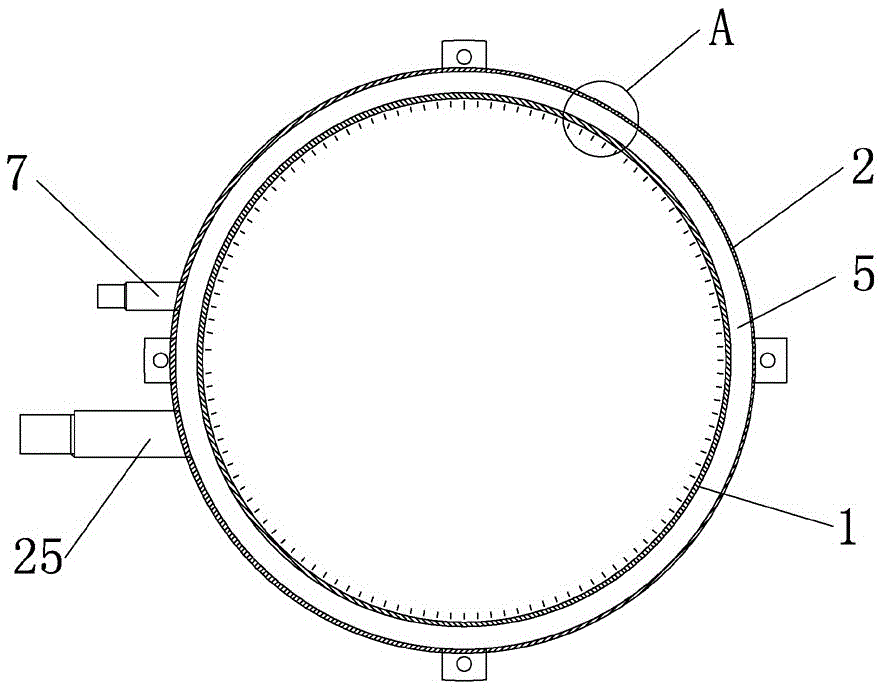
[0023] combine figure 1 with image 3 , an evaporator for a seawater flake ice machine, comprising an inner cylinder 1 and an outer cylinder 2, an annular cavity 5 is formed between the inner cylinder 1 and the outer cylinder 2, and an annular stepped ascending passage is arranged in the annular cavity 5 to form a refrigeration chamber 9. The cavity 9 is divided into two sections from top to bottom by a partition 100, and a refrigerant outlet 8 is provided on the outer cylinder wall 20 corresponding to the lower part of each section, and a refrigerant inlet 7 is provided on the corresponding outer cylinder wall 20 at the upper part, forming The ratio of the height H to the width L of the cross-section of the annular ascending channel of the refrigeration chamber 9 is 1:1.1.
[0024] During the working process, the refrigerant enters the refrigeration chamber 9 from the refrigerant inlet 7, flows in the refrigeration chamber 9, and flows out from the refrigerant outlet 8; at t...
Embodiment 2
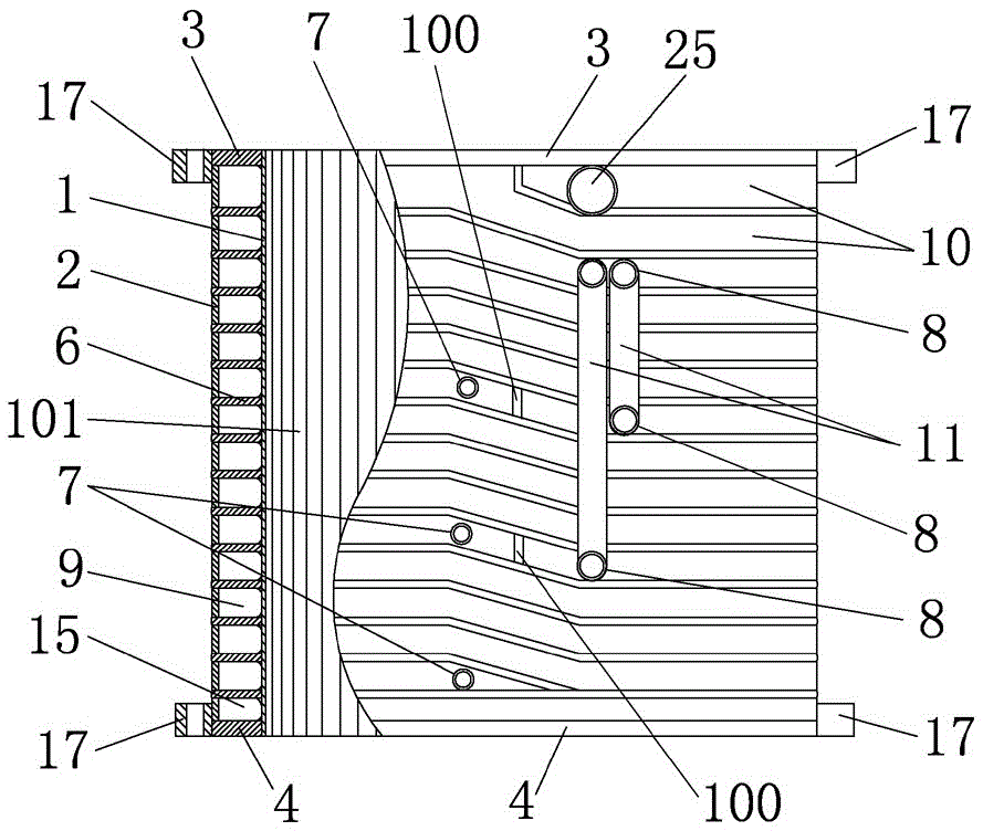
[0026] The difference from Embodiment 1 is that the refrigeration chamber 9 is divided into three sections from top to bottom by the partition plate 100, and the outer cylinder wall 20 corresponding to the lower part of each section is provided with a refrigerant outlet 8, and the outer cylinder wall 20 corresponding to the upper part There is a refrigerant inlet 7 (such as figure 2 As shown), the ratio of the height H to the width L of the cross-section of the annular ascending channel forming the refrigeration chamber 9 is 1:1.35.
Embodiment 3
[0028] The difference from Embodiment 1 is that there is no partition 100 in the refrigeration chamber 9, and only a refrigerant inlet 7 is provided on the outer cylinder wall 20 corresponding to the lower part of the refrigeration chamber 9, and a refrigerant inlet 7 is provided on the corresponding outer cylinder wall 20 at the upper part of the refrigeration chamber 9. Exit 8 (eg Figure 5 shown), wherein the refrigerant outlet 8 communicates with the pre-cooling chamber. The ratio of the height H to the width L of the cross-section of the annular ascending channel forming the refrigeration chamber 9 is 1:1.7.
[0029] In order to embody the remarkable technical effect of the present invention in terms of ice-making efficiency, the inventor also adopted the ratio of the height H and the width L of the cross-section of the annular ascending channel forming the refrigeration cavity 9 in three prior art (specifically 1 :0.3, 1:0.7 and 1:0.85, other conditions are the same as ...
PUM
 Abstract
Description
Claims
Application Information
 - R&D
- Intellectual Property
- Life Sciences
- Materials
- Tech Scout
- Unparalleled Data Quality
- Higher Quality Content
- 60% Fewer Hallucinations
Browse by: Latest US Patents, China's latest patents, Technical Efficacy Thesaurus, Application Domain, Technology Topic, Popular Technical Reports.
© 2025 PatSnap. All rights reserved.Legal|Privacy policy|Modern Slavery Act Transparency Statement|Sitemap|About US| Contact US: help@patsnap.com


