Method and fossil-fuel-fired power plant for recovering a condensate

A technology for fossil fuels and power plants, applied in separation methods, chemical instruments and methods, through absorption, etc., can solve problems such as high investment and operating costs, high costs, etc.

Inactive Publication Date: 2014-04-09
SIEMENS AG
View PDF9 Cites 0 Cited by
  • Summary
  • Abstract
  • Description
  • Claims
  • Application Information

AI Technical Summary

Problems solved by technology

In order to prepare this water partly incurs high costs
For supplementary equipment with CO 2 As far as the power station of the separator is concerned, the soft water preparation device must be provided in the same process at the same time, which brings high investment and operating costs

Method used


Image

  • Method and fossil-fuel-fired power plant for recovering a condensate
  • Method and fossil-fuel-fired power plant for recovering a condensate

Examples


Embodiment Construction

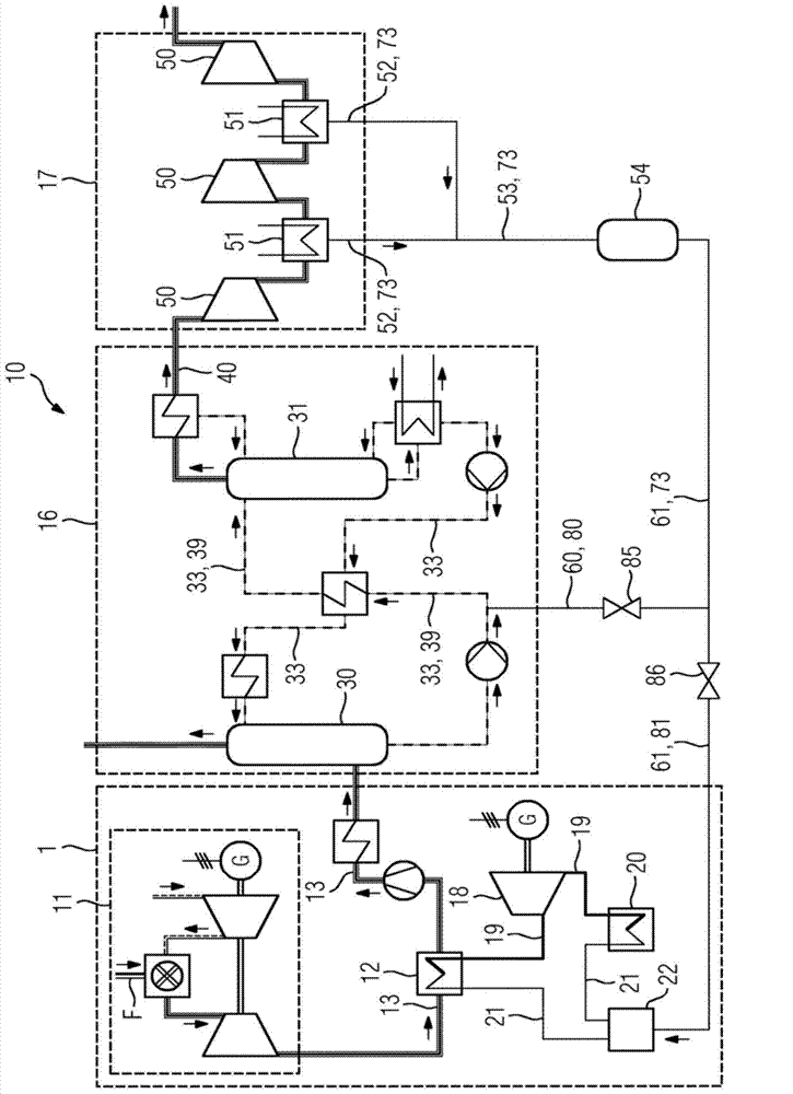
[0020] figure 1 Represents a fossil fuel-burning power station 10, which has a gas turbine equipment as a combustion device 11, a waste heat boiler 12 connected to the gas turbine downstream of the combustion device 11 through a flue gas channel 13, a condenser 20, a soft water preparation device 22, connected to the smoke CO in air channel 13 2 Separator 16, and connected to CO 2 The compressor 17 downstream of the separator 16 has a certain number of compression stages and intermediate cooling stages 50 and 51.

[0021] The fossil fuel is burned in the gas turbine of the combustion device 11, and CO-containing 2 Smoke. The flue gas is supplied to the waste heat boiler 12 through the flue gas channel 13 for generating steam 19. The steam 19 is fed to a steam turbine plant 18 not shown in detail here, where the steam 19 is expanded and then sent to the condenser 20 and reduced in pressure into feed water 21. After the steam 19 is condensed in the condenser 20, the feed water 21 ...


PUM


Abstract

The invention relates to a fossil-fuel-fired power plant (10), comprising a combustion device (11), a CO2 separation device (16), which is arranged downstream of the fossil-fuel-fired power plant (10), for removing CO2, and a CO2 compressor station (17), which is arranged downstream of the CO2 separation device (16) and which has a number of compressor stages (50) and coolers (51) for intermediate cooling. According to the invention, the coolers (51) are connected to the CO2 separation device (16) or the fossil-fuel-fired power plant (10) by means of a condensate line (52, 53, 60, 61) in order to recover condensate. The invention further relates to a method for carrying out the condensate recovery.

Description

Technical field [0001] In a fossil fuel-burning power station for power generation, a flue gas containing carbon dioxide is produced by burning fossil fuel. To avoid or reduce carbon dioxide emissions, carbon dioxide must be separated from the flue gas. In order to separate carbon dioxide from a gas mixture, several different methods are known. Especially in order to separate carbon dioxide from the flue gas after the combustion process, the absorption-desorption method is commonly used. In large-scale industries, carbon dioxide is washed out of flue gas with the help of solvents (CO 2 Absorption process). Background technique [0002] Commonly used absorbents are aqueous solutions of detergent additives, such as Methanlolamin (MEA), amino acid salts or potash. These detergent additives show that carbon dioxide (CO 2 ) It has good selectivity and high capacity. [0003] But in the CO 2 During the absorption process, part of the water is always continuously evaporated. Water va...

Claims


Application Information

Patent Timeline
Patent Type & Authority Applications(China)
IPC IPC(8): F01K23/10
CPCB01D53/002F23J15/02Y02C10/06F01K23/10B01D53/1475Y02C20/40Y02E20/32
Inventor R.施奈德H.施拉姆
Owner SIEMENS AG
Why Eureka
Try Eureka