Antenna module group

An antenna module and antenna technology, applied in the direction of antenna support/installation device, clamping/spring connection, etc., can solve the problem of conductive foam printed circuit board falling off, printed circuit board broken, and poor contact between the printed circuit board and the antenna And other issues

Inactive Publication Date: 2014-04-09
UNIVERSAL SCIENTIFIC INDUSTRIAL (SHANGHAI) CO LTD +1
View PDF12 Cites 1 Cited by
  • Summary
  • Abstract
  • Description
  • Claims
  • Application Information

AI Technical Summary

Problems solved by technology

[0003] However, as far as the contact metal shrapnel is concerned, the contact metal shrapnel is prone to elastic deformation under long-term stress, which will cause poor contact between the printed circuit board and the antenna, and the conductive foam itself is easy to dissipate from the printed circuit board If it falls off, it will also affect the electrical conduction effect between the printed circuit board and the antenna
Moreover, in order to fix the antenna itself, the printed circuit board must also be provided with a plurality of screw holes to match the screws to fix the antenna itself or the supporting seat to which the antenna is attached. These screw hole posts will occupy too much space and limit the space of the printed circuit board. In addition to the circuit design, it is also easy to cause the printed circuit board to be broken during the installation process, which will increase the manufacturing cost; therefore, no matter whether it is a contact metal shrapnel or a conductive foam, there is no way to provide good electrical power to the antenna. Sexual function, taking into account the fixed effect

Method used


Image

  • Antenna module group
  • Antenna module group
  • Antenna module group

Examples


Embodiment Construction

[0026] In order to explain in detail the structure, features and effects of the present invention, two preferred embodiments are listed here and the following descriptions are made in conjunction with the following drawings.

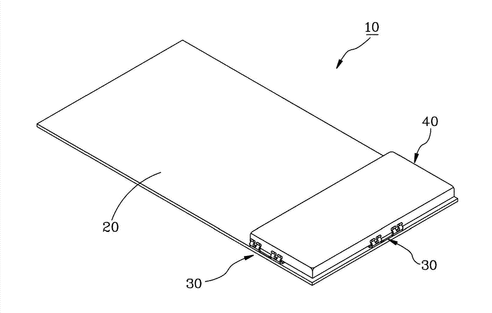
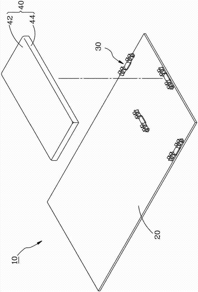
[0027] figure 1 with figure 2 The antenna module 10 according to the first preferred embodiment of the present invention includes a printed circuit board 20, a plurality of conductive clips 30, and an antenna 40. The printed circuit board 20 is a well-known structure and will not be described here.

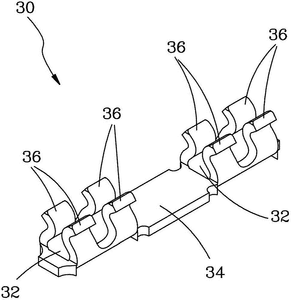
[0028] Such as image 3 As shown, each conductive clip 30 has two bases 32, the two bases 32 are connected together by a picking portion 34, and the two bases 32 respectively extend from the surface toward a direction away from the printed circuit board 20. On the elastic clamp arm 36. When the electrical connection is made with the printed circuit board 20, the pick-up portion 34 of each conductive clip 30 is clamped by a robot arm, and then the above-mentioned...


PUM


Abstract

The invention relates to an antenna module group mainly comprising a printed circuit board, a plurality of conductive clamp elements, and an antenna. All the conductive clamp elements are arranged at the printed circuit board and each conductive clamp element has two opposite elastic clamp arms. The antenna can be plugged between the elastic clamp arms of the conductive clamp elements by a detachable way. Therefore, assembling of the antenna with the printed circuit board can be realized by the conductive clamp elements, and with utilization of the conductive clamp elements, the signal feeding and grounding can be realized, so that effects of convenient assembling and disassembling and the configuration elasticity enhancement can be realized.

Description

Technical field [0001] The present invention relates to an antenna used in a handheld electronic device, and in particular refers to an antenna module that uses a conductive clip as the feed point and / or ground point of the antenna while providing a fixed clamping function. Background technique [0002] Generally speaking, handheld electronic devices, such as portable bar code scanners, require an antenna to be installed inside the body to transmit and receive wireless signals. The traditional antenna is set up by multiple contact metal shrapnel or multiple conductive foams fixed to the printed circuit board with Surface Mount Technology (SMT), so that the antenna can pass through the contact metal shrapnel or conductive foam. Touch to complete the electrical conduction with the printed circuit board, and then complete the feeding and grounding of the antenna signal. [0003] However, as for the contact metal shrapnel first, the contact metal shrapnel is prone to elastic deformati...

Claims


Application Information

Patent Timeline
IPC IPC(8): H01Q1/22H01R4/48
Inventor 李政达简瑞志邱弘伟
Owner UNIVERSAL SCIENTIFIC INDUSTRIAL (SHANGHAI) CO LTD
Why Eureka
Try Eureka