
Bistable permanent magnetic mechanism

A permanent magnet mechanism and bistable technology, applied in the direction of high-voltage air circuit breakers, electrical components, electric switches, etc., can solve the problems of increasing the movement conversion link, increasing the difficulty of design, reducing the working efficiency and reliability of the mechanism, and achieving the guarantee Reliability and the effect of improving the suction force

Active Publication Date: 2014-04-09
COOPER EDISON PINGDINGSHAN ELECTRONICS TECH
View PDF5 Cites 2 Cited by
  • Summary
  • Abstract
  • Description
  • Claims
  • Application Information

AI Technical Summary

Problems solved by technology

The increased motion conversion link reduces the working efficiency and reliability of the mechanism and increases the difficulty of design

Method used


Image

  • Bistable permanent magnetic mechanism
  • Bistable permanent magnetic mechanism
  • Bistable permanent magnetic mechanism

Examples


Embodiment Construction

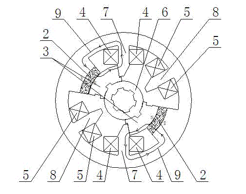
[0019] Such as figure 2 As shown, a bistable permanent magnet mechanism includes an outer yoke 1 with a circular inner cavity and a mandrel 6 arranged at the center of the outer yoke 1, the mandrel 6 is made of a non-magnetic material, Two moving iron cores 3 that are not connected to each other are arranged symmetrically on the circumference of the mandrel 6, and on the inner wall of the outer yoke 1, a closing pole 7 is provided corresponding to both sides of each moving iron core 3 and a gate-opening pole 8, the gate-closing pole 7 and the gate-opening pole 8 are provided with a working surface that can be attracted to the moving iron core 3, and the gate-closing pole 7 and the gate-opening pole 8 are respectively wound with a The moving iron core 3 reciprocates between the closing pole 7 and the opening pole 8, the closing coil 4 and the opening coil 5, and the inner wall of the outer yoke 1 is provided with a coil that is always in contact with the outer surface of the m...


PUM


Abstract

The invention relates to a bistable permanent magnetic mechanism. The bistable permanent magnetic mechanism comprises an outer magnet yoke and a mandrel arranged in the center of the outer magnet yoke, the mandrel is made of non-magnetically conductive material, two unconnected movable iron cores are symmetrically arranged on the circumference of the mandrel, both a closing pole and an opening pole are arranged are arranged on an inner wall of the outer magnet yoke corresponding to two sides of each of movable iron cores, both the closing poles and the opening poles are provided with working faces capable of being attracted to the movable iron cores and are wound by closing coils and opening coils for driving the movable iron cores to perform reciprocating motion between the closing poles and the opening poles, permanent magnets which always correspond to outer side faces of the movable iron cores in the movement process thereof are arranged on the inner wall of the outer magnet yoke, and the permanent magnets separate the movable iron cores from the inner wall of the outer magnet yoke. In the bistable permanent magnetic mechanism, permanent magnetic flux generated by the permanent magnets is not shorted by the outer magnet yoke, and the movable iron cores are ensured to have enough magnetic flux passing through the working face of the closing poles or the opening poles, thereby ensuring the movable iron cores to be kept in locking positions of the closing poles or the opening poles, and ensuring reliability of closing or opening operation.

Description

technical field [0001] The invention relates to the technical field of electrical appliances, and is particularly suitable as an operating mechanism of a vacuum circuit breaker in a gas-insulated box-type fixed cabinet, specifically a bistable permanent magnet mechanism. Background technique [0002] The permanent magnet mechanism has few moving parts, simple structure and high reliability, and is especially suitable for vacuum circuit breakers that require frequent operations or long mechanical life. At present, most vacuum circuit breakers, especially indoor vacuum circuit breakers, require an operating mechanism for rotating output, while the permanent magnet mechanism of the prior art outputs linear motion, such as figure 1 As shown, the left yoke 101 and the right yoke 601 are respectively arranged on both sides of the outer yoke 301, the opening coil 201, the permanent magnet 401 and the closing coil 501 are sequentially arranged inside the outer yoke 301, and then the...

Claims


Application Information

Patent Timeline
IPC IPC(8): H01H33/666
Inventor 刘坤王竹云芮祖存
Owner COOPER EDISON PINGDINGSHAN ELECTRONICS TECH
Learn More