Crosslapper and method for operating crosslapper

A cross-lapper and web-laying technology, which is applied in the direction of rolling mechanism, textile and papermaking, fiber processing, etc., can solve the problems of increasing operating costs and investment costs, and achieve the effect of avoiding stretching

Active Publication Date: 2014-04-09
TRUETZSCHLER GRP SE
View PDF6 Cites 6 Cited by
  • Summary
  • Abstract
  • Description
  • Claims
  • Application Information

AI Technical Summary

Problems solved by technology

Suction deflection rolls increase operating costs and investment costs due to expensive roll construction

Method used


Image

  • Crosslapper and method for operating crosslapper
  • Crosslapper and method for operating crosslapper

Examples


Embodiment Construction

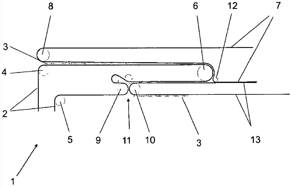
[0023] figure 1 The principle of a crosslapper according to the prior art is shown by way of example and only schematically. The fiber fleece 3 is transported by a carding device (not shown) onto the feed belt 2 of the crosslapper 1 . An upper carriage is arranged in the crosslapper 1 , only one deflection roller 6 being visible in this view. Furthermore, the crosslapper 1 has a laying carriage, in which a laying roller 10 for the reverse belt 13 and a laying roller 9 for the feed belt 2 are shown. Between the laying roller 10 of the reverse belt 13 and the laying roller 9 of the feed belt 2 there is a so-called laying nip 11, from which the fiber fleece 3 emerges and is deposited on the laying roller 9 arranged on said laying nip. on a belt not shown below the carriage. Depending on the direction of travel, the two laying rollers 9, 10 undertake the task of depositing the fiber fleece 3 perpendicular to the current direction of travel on a belt arranged below the laying ca...


PUM


Abstract

The invention relates to a crosslapper used for formation of a fleece made of many layers of fibrous web. The crosslapper comprises at least one continuously revolving input belt (2) which supplies the fibrous web (3) from the inlet region of the crosslapper up to a laying gap (11) of the laying carriage, and a continuously circulating cover belt (7) which fixes the fibrous web (3) on the input belt (2). The crosslapper is characterized in that the cover belt (7) fixes the fibrous web (3) from the inlet region of the crosslapper (1) up to the laying gap on the input belt(2).

Description

technical field [0001] The invention relates to a crosslapper for forming nonwovens from multiple layers of fiber fleece. [0002] Furthermore, the invention relates to an associated method for operating a crosslapper. Background technique [0003] For the production of multilayer nonwovens, carding lines with subsequent crosslappers are usually used. In these carding devices, fiber tufts are conveyed to the supply side, these fiber tufts are disassembled into individual fibers and are delivered as unconsolidated fabric flat objects—fiber tufts—on the outlet side. [0004] In order to take full advantage of the available card performance, it is necessary to increase the pile speed (Florgeschwindigkeit) in the downstream crosslapper. However, high centrifugal forces occur here on the deflection rollers of the laying belt, which significantly reduce the quality properties of the fiber fleece depending on the direction of travel and the belt speed. [0005] In the web laying...

Claims


Application Information

Patent Timeline
Patent Type & Authority Applications(China)
IPC IPC(8): D04H1/74
CPCD01G25/00
Inventor B·吕贝纳赫
Owner TRUETZSCHLER GRP SE
Why Eureka
Try Eureka