a recumbent bicycle
A bicycle and frame technology, applied in the field of prone bicycles, can solve the problems of unfavorable venous blood return of lower extremities, increase the compression strength of human spine, buttock discomfort, etc., so as to be beneficial to long-distance riding, improve riding efficiency, and reduce side effects Effect
- Summary
- Abstract
- Description
- Claims
- Application Information
AI Technical Summary
Problems solved by technology
Method used
Image
Examples
Embodiment 1
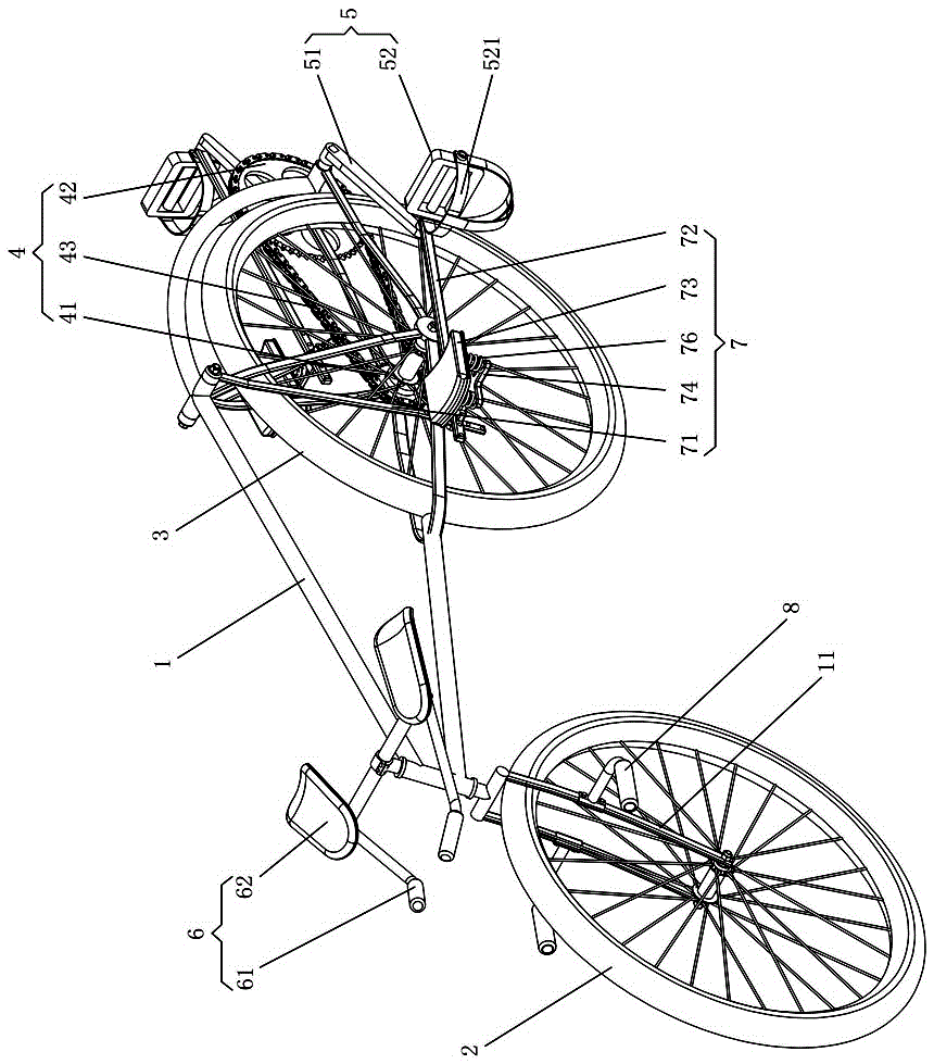
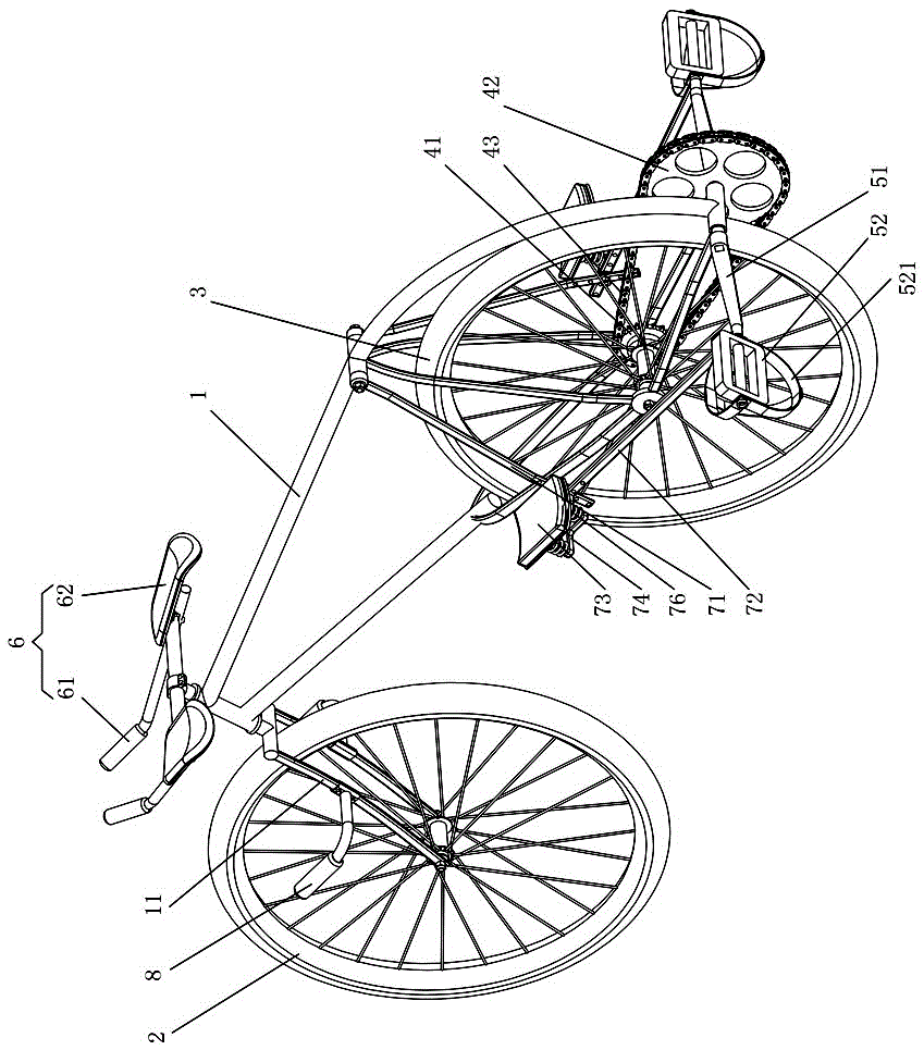
[0058] Example 1: figure 1 and figure 2 The first embodiment of the prone bicycle of the present invention is shown, and the prone bicycle comprises a vehicle frame 1, a front wheel 2, a rear wheel 3, a transmission mechanism 4 for driving the rear wheel 3, and a transmission mechanism 4 for driving the transmission mechanism 4. The pedaling mechanism 5, the front wheel 2 and the rear wheel 3 are respectively arranged on the front and the rear of the vehicle frame 1, the front of the vehicle frame 1 is provided with a forearm support mechanism 6, and the pedaling mechanism 5 and the vehicle frame 1 are provided with a Knee dynamic support mechanism 7 that moves synchronously with stepping on mechanism 5. We have found through the analysis of the prior art that it is difficult to satisfactorily solve the support problem of the rider's body in the prone position only by relying on static support. The present invention is based on human anatomy, bionics and ergonomics, and care...
Embodiment 2
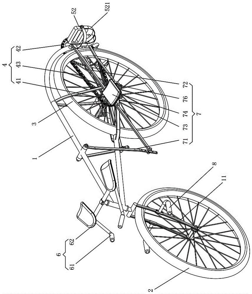
[0062] Example 2: image 3 and Figure 4 The second prone bicycle embodiment of the present invention is shown. This embodiment is basically the same as Embodiment 1, the only difference being that the knee dynamic support mechanism 7 includes a pair of swing bars 71, A pair of connecting rods 72 and a pair of knee support pads 73, the upper ends of each swing rod 71 are hinged on the middle and upper part of the vehicle frame 1, one end of each connecting rod 72 is hinged with the lower end of the swing rod 71, and the other end is hinged with the crank 51, and is located in the active position. The fork 71, connecting rod 72 and crank 51 on the same side of the sprocket wheel 42 form a set of crank rocker mechanism, and each knee support pad 73 is suspended and installed on the middle part of the connecting rod 72 by a support 74. The length is longer, and the middle part is provided with a plurality of adjustment holes, so that the position of the knee support pad 73 can b...
Embodiment 3
[0064] Example 3: Figure 5 and Figure 6 The third prone bicycle embodiment of the present invention is shown. This embodiment is basically the same as Embodiment 2, the only difference being that the knee dynamic support mechanism 7 includes a pair of swing bars 71, A pair of connecting rods 72 and a pair of knee support pads 73, the upper ends of each swing rod 71 are hinged on the middle and upper part of the vehicle frame 1, one end of each connecting rod 72 is provided with a U-shaped connector 721, and the U-shaped connector 721 is connected to the pedal The rotating shaft of 52 is hinged, and the other end of each connecting rod 72 is also provided with a U-shaped structure, and is hinged with the lower end of the swing rod 71 through the U-shaped structure. One set of crank rocker mechanism, each knee support pad 73 is installed in the middle part of connecting rod 72 by a seat 74, and the bearing fulcrum of knee support pad 73 and support seat 74 is positioned at th...
PUM
 Abstract
Description
Claims
Application Information
 - R&D
- Intellectual Property
- Life Sciences
- Materials
- Tech Scout
- Unparalleled Data Quality
- Higher Quality Content
- 60% Fewer Hallucinations
Browse by: Latest US Patents, China's latest patents, Technical Efficacy Thesaurus, Application Domain, Technology Topic, Popular Technical Reports.
© 2025 PatSnap. All rights reserved.Legal|Privacy policy|Modern Slavery Act Transparency Statement|Sitemap|About US| Contact US: help@patsnap.com


