
Diffusion drainage device of range hood

A range hood and oil fume technology, which is applied in the field of pressure diffusion and drainage devices, can solve problems such as increased user complaints, backflow of smoke, high back pressure, etc., and achieve the effect of improving the diffusion of oil fume and improving the pressure distribution

Active Publication Date: 2014-04-02
NINGBO FOTILE KITCHEN WARE CO LTD
View PDF11 Cites 26 Cited by
  • Summary
  • Abstract
  • Description
  • Claims
  • Application Information

AI Technical Summary

Problems solved by technology

During the peak hours of cooking, when multiple users in the same unit cook together and turn on the range hood, due to the limited volume in the shared flue, the internal back pressure is high. Generally, due to the increase of the outlet resistance, the working point of the centrifugal fan that generates negative pressure is biased towards the working area with small flow rate, resulting in the extreme deterioration of the oil suction fume effect, greatly enhanced noise, poor sound quality, and increased user complaints
[0004] In order to solve the above problems, the current technical status is mostly to increase the air volume of the fan as the main technical means to improve the effect of oil absorption fume. However, from the above analysis, we can see that the more the air volume is increased, the shared The resistance in the flue will be greater, which will further deteriorate the performance of the fan, and for some range hood users with small air volume, the problem of flue gas backflow will also occur

Method used


Image

  • Diffusion drainage device of range hood
  • Diffusion drainage device of range hood
  • Diffusion drainage device of range hood

Examples


Embodiment 1

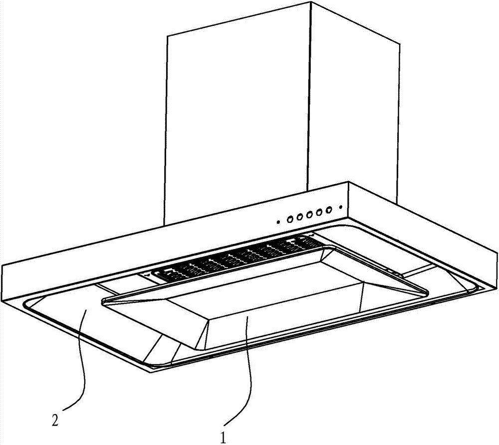
[0027] Such as figure 1 The shown smoke guiding device of the top suction range hood includes a diffuser and drainage smoke control plate 1 which is arranged facing the air inlet of the smoke collection hood of the top suction range hood, and the inside of the smoke collection hood 2 of the top suction range hood is A smoke collection cavity is formed, and the diffuser and drainage smoke control plate 1 has a concave structure with a high center and a low periphery, so that the diffuser and drainage smoke control plate 1 is combined with the smoke collection hood 2 to make the collection of the top suction range hood The smoke cavity is formed with two upper and lower double-layer concave cavities, which also makes the caliber of the oil fume channel formed between the diffuser and drainage smoke control plate and the smoke collection hood gradually shrink.

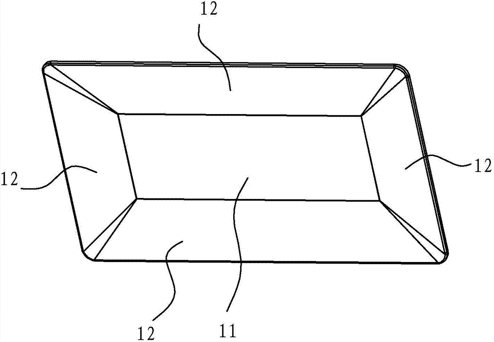
[0028] In this embodiment, the diffuser and drainage smoke control plate 1 includes a middle plane 11 and surrounding s...

Embodiment 2

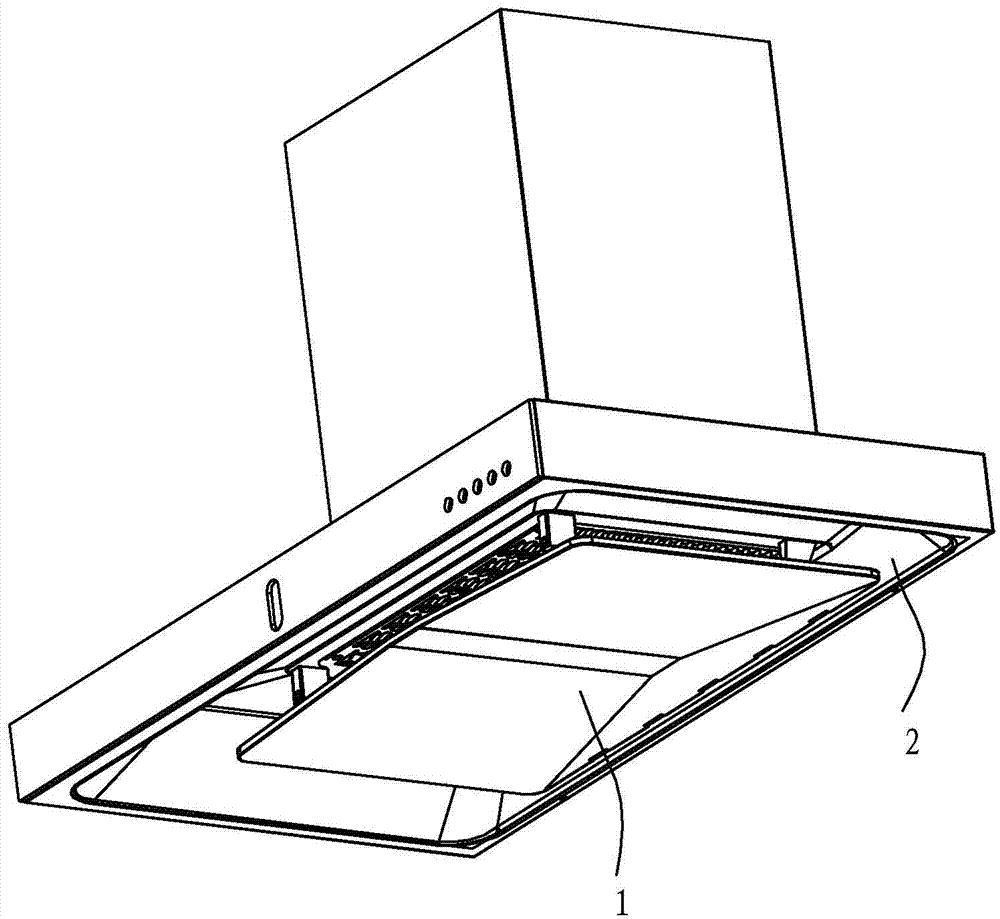
[0031] The difference from Embodiment 1 is that the rear side of the diffuser and drainage smoke control plate 1 is hinged on the smoke collection hood 2, and the front side of the diffuser pressure drainage smoke control plate 1 is connected with the smoke collection hood 2 through buckles 3, see image 3 , 4 As shown, and in this embodiment, the area of ​​the middle plane 11 of the diffuser and drainage smoke control plate 1 is smaller than the area of ​​the middle plane in Embodiment 1, see Figure 5 shown.

Embodiment 3

[0033] The difference from Embodiment 1 is that when the diffuser and drainage smoke control plate 1 is installed, the front side is higher and the rear side is lower, and the diffuser and drainage smoke control plate 1 is provided with a strip-shaped oil cup 4 at the rear, see Figure 6 shown. The diffuser, drainage, and smoke control plate 1 is inclined backward, and a strip-shaped oil cup is arranged on the rear side, which is convenient for guiding oil and accepting and storing oil.


PUM


Abstract

The invention relates to a diffusion drainage device of a range hood. The diffusion drainage device comprises a diffusion drainage smoke control plate which is just opposite to an exhaust fume collecting hood air inlet of the ceiling type range hood, and is characterized in that the diffusion drainage smoke control plate has an inwards concave structure with a high middle part and a low periphery. Compared with the prior art, the diffusion drainage device disclosed by the invention has the advantages that the diffusion drainage smoke control plate having the inwards concave structure with the high middle part and the low periphery can ensure that the pressure distribution on the lower side and the edges of the range hood is improved and reconstructed; compared with a conventional range hood, the range hood has the advantages that the periphery of the diffusion drainage smoke control plate has a venturi effect to ensure that negative pressure is expanded outwards to the edges of the diffusion drainage smoke control plate, and an effective area for sucking oil fume is enlarged by about twice; after oil fume gas rises and contacts the edges of the diffusion drainage smoke control plate, the oil fume gas can move upwards quickly, a negative pressure passage is defined by the diffusion drainage smoke control plate and the inner surface of a smoke collecting cavity at the upper part of the diffusion drainage smoke control plate at the same time, and then the oil fume gas flows inwards to an air inlet of a blower along the negative pressure passage; by virtue of the inwards concave area, the oil smoke diffusion is greatly promoted.

Description

technical field [0001] The invention relates to a diffuser and drainage device for a range hood. Background technique [0002] At present, most of the existing top-suction range hoods (thin, deep or tower range hoods installed directly above the stove, excluding side suction and bottom row types) mostly have the following structural forms: a smoke collection hood is set on the top to form Inner concave cavity, air inlet and filter screen are set on the smoke collecting hood; there is also a type of range hood, such as: ZL200910096759.3 "A range hood with smoke guide plate", which is characterized in that the inner cavity A smoke deflector with a planar structure is arranged at the bottom. However, both of these two main types of top suction range hoods have the problem of not being able to absorb the oil fume. When a large amount of oil fume is generated, the oil fume tends to spread in large quantities from the front, left and right sides. In addition, these types of rang...

Claims


Application Information

Patent Timeline
Patent Type & Authority Applications(China)
IPC IPC(8): F24C15/20
Inventor 李斌董一龙任树栋胡承杰茅忠群诸永定
Owner NINGBO FOTILE KITCHEN WARE CO LTD
Learn More