A pressure gauge seat moving mechanism

A technology of moving mechanisms and pressure gauges, which is applied in metal processing, metal processing equipment, manufacturing tools, etc., can solve the problems of reducing production costs and achieve the effects of reducing production costs, high positioning accuracy, and reducing labor intensity

Active Publication Date: 2016-04-06
BOZHON PRECISION IND TECH CO LTD
View PDF5 Cites 0 Cited by
  • Summary
  • Abstract
  • Description
  • Claims
  • Application Information

AI Technical Summary

Problems solved by technology

reduce manufacturing cost

Method used


Image

  • A pressure gauge seat moving mechanism
  • A pressure gauge seat moving mechanism
  • A pressure gauge seat moving mechanism

Examples


Embodiment Construction

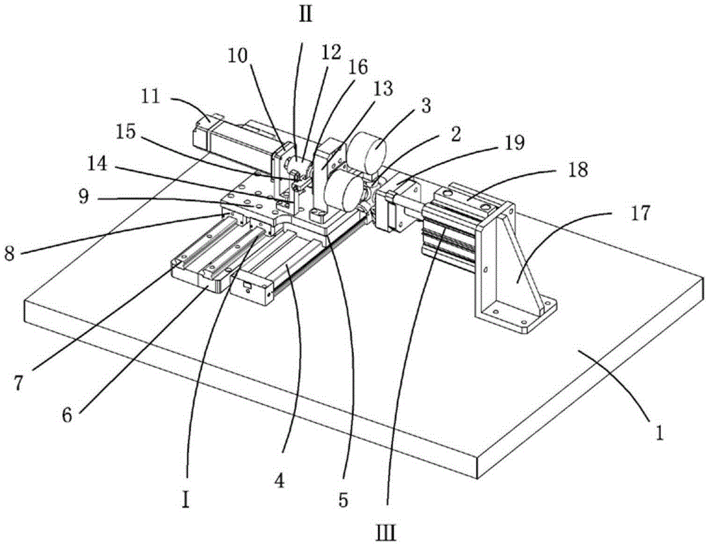
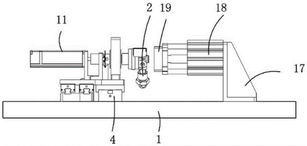
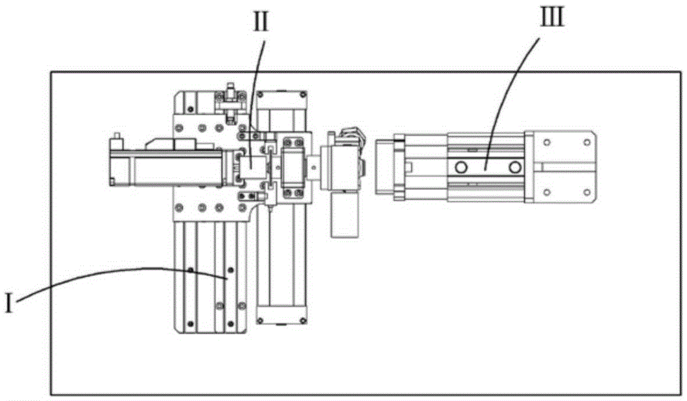
[0019] Examples, see attached Figure 1~3 , a moving mechanism for a pressure gauge seat, which includes a base plate 1, a moving module I, a rotating module II, a clamping module III, a pressure gauge seat 2 and a pressure gauge 3, and the moving module and the clamping module are respectively It is installed on the bottom plate; the rotary module is installed on the mobile module; the pressure gauge seat is positioned on the rotary module through a clamp; four pressure gauges can be installed on the pressure gauge seat.

[0020] The mobile module includes a mobile cylinder 4, a mobile block 5, a slide rail holder 6, a slide rail 7, a slide block 8 and a mounting plate 9, and the mobile cylinder and the slide rail holder are installed on the base plate respectively, and the mobile cylinder parallel to the slide rail fixing seat; a moving block is installed on the moving cylinder; two slide rails are installed side by side on the slide rail fixing seat, and a slider is install...


PUM


Abstract

The invention relates to a pressure meter seat moving mechanism, comprising a bottom plate, a mobile module, a rotary module, a clamping module, a pressure meter seat and a pressure meter; the mobile module and the clamping module are arranged on the bottom plate respectively; the rotary module is arranged on the mobile module; the pressure meter seat is positioned on the rotary module by a clamp; the pressure meter is mounted on the pressure meter seat; a mobile cylinder of the mobile module drives the pressure meter seat to a machining position; the direction of the pressure meter seat is rotated to a designated position by the rotary module, then a clamping cylinder clamps the pressure meter seat and ensures that the pressure meter seat is not loosened in the use process, and the pressure meter seat can freely rotate in the rotation process. The pressure meter seat moving mechanism can perform rotation motion while clamping, the rotating positioning precision is high, and a work position is not deviated as a rotary motor of the rotary module can be braked. The labor intensity of operation staff is reduced, and the production cost is reduced.

Description

Technical field: [0001] The invention relates to the field of moving mechanism equipment, and more specifically relates to a mechanism capable of clamping and moving a pressure gauge base while performing rotational movement. Background technique: [0002] When assembling the pressure gauge seat and the pressure gauge together, the pressure gauge needs to be rotated and assembled to the corresponding position of the pressure gauge seat, and the torque value required by the product must be achieved. The assembly process of the prior art requires manual transportation of the pressure gauge seat, and Adjusting the working angle of the pressure gauge seat, but the manual operation is labor-intensive and the assembly precision is low, which cannot guarantee the product quality, thereby increasing the production cost. Invention content: [0003] The purpose of the present invention is to provide a moving mechanism for the pressure gauge base against the deficiencies of the prior...

Claims


Application Information

Patent Timeline
Patent Type & Authority Patents(China)
IPC IPC(8): B23P19/00
CPCB23P19/001B23P19/002B23P19/006
Inventor 吕绍林蔡志敏罗凯闻黄巍
Owner BOZHON PRECISION IND TECH CO LTD
Why Eureka
Try Eureka