
switching power supply unit

A technology of switching power supply and switching element, which is applied in the direction of output power conversion devices, electrical components, and regulating electrical variables.

Active Publication Date: 2016-03-30
SANKEN ELECTRIC CO LTD
View PDF4 Cites 0 Cited by
  • Summary
  • Abstract
  • Description
  • Claims
  • Application Information

AI Technical Summary

Problems solved by technology

[0006] The present invention solves the above-mentioned problems of the prior art in view of the above-mentioned problems, and its object is to provide a switching power supply device that can be used for smooth switching after rectification of an AC power supply without increasing power consumption during normal operation. Transient Recovery Voltage Discharge of Electrolytic Capacitors

Method used


Image

  • switching power supply unit
  • switching power supply unit
  • switching power supply unit

Examples


Embodiment Construction

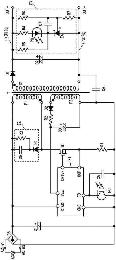
[0045] refer to figure 1 , The switching power supply device of this embodiment has a rectifier circuit DB, electrolytic capacitors C1, C2, C3, switching element Q1, transformer T, rectifier diodes D1, D2, resistors R1, R2, capacitors C4, C5, control circuit Z1, snubber circuit Z2, feedback circuit Z3.

[0046] The AC input terminals ACin1 and ACin2 of the rectifier circuit DB constituted by bridge diodes are connected to the AC power source AC, and the AC voltage input from the AC power source AC is full-wave rectified and output from the rectifier circuit DB. An electrolytic capacitor C1 is connected between the rectification output positive terminal and the rectification output negative terminal of the rectification circuit DB. In this way, a DC power supply in which the AC power supply AC is rectified and smoothed by the rectifier circuit DB and the electrolytic capacitor C1 can be obtained.

[0047] Between the positive terminal and the negative terminal of the electro...


PUM


Abstract

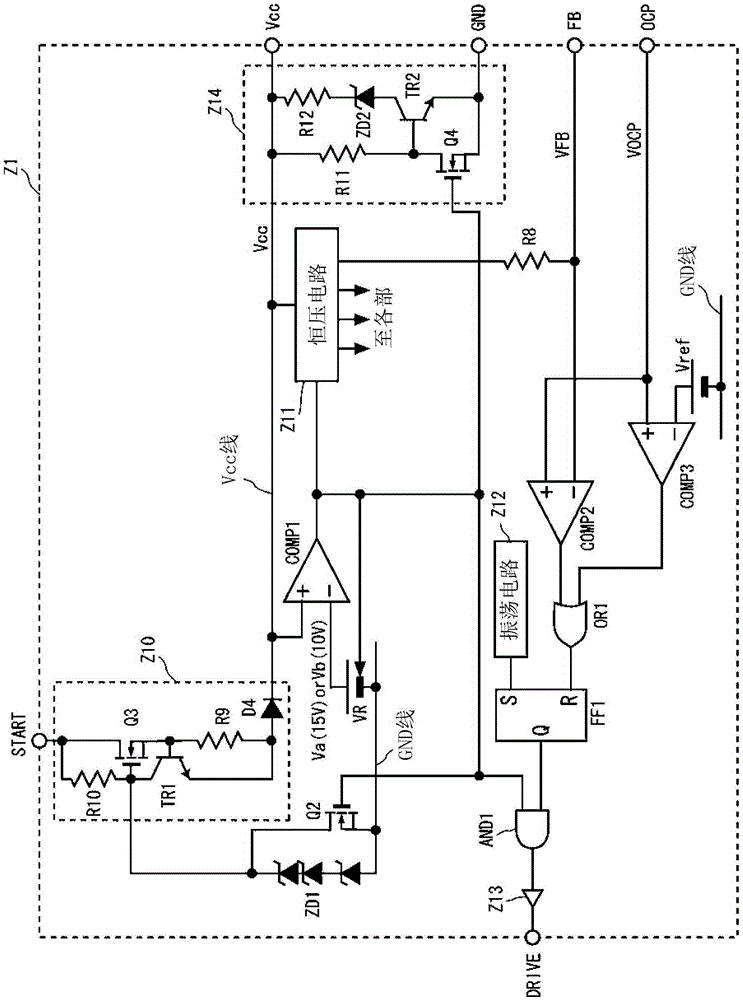
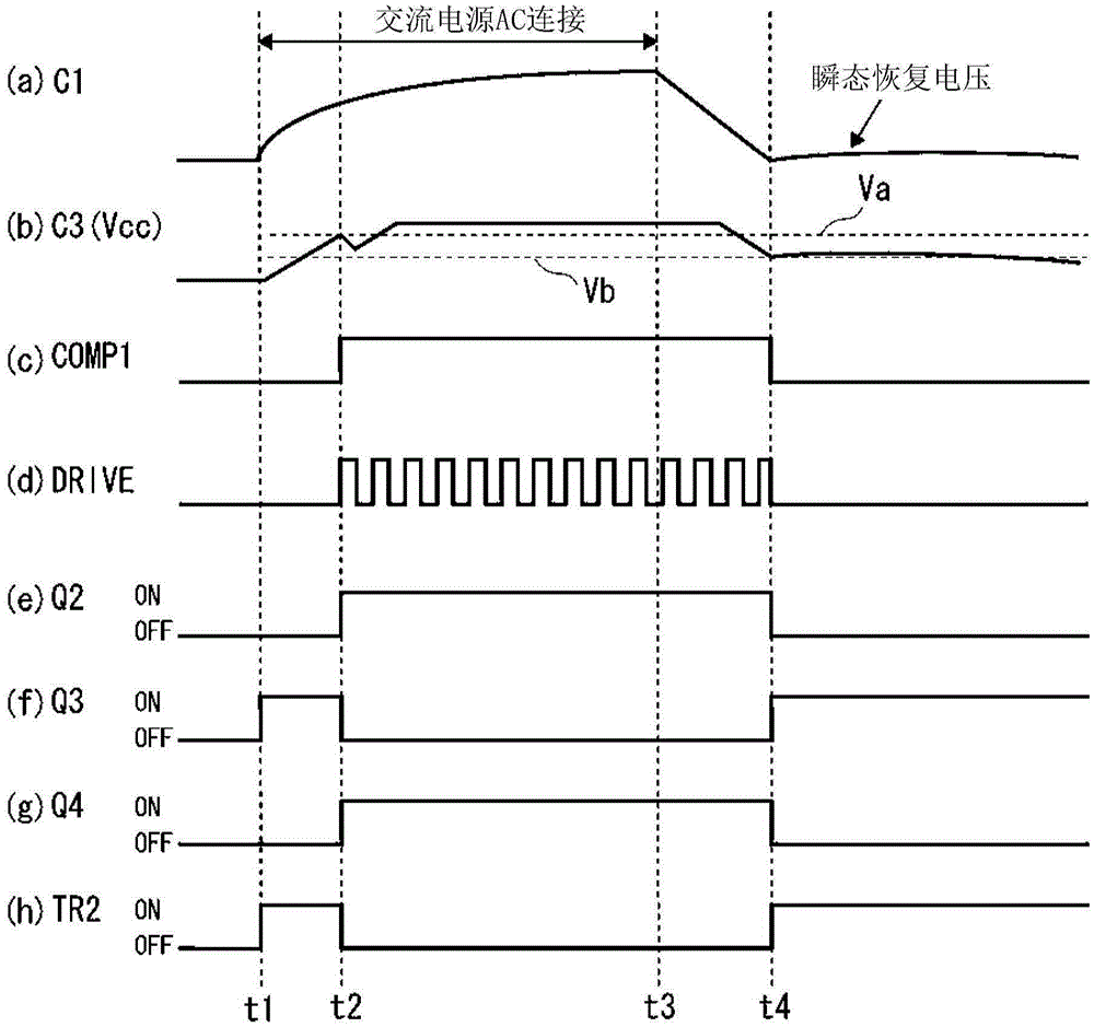
The invention provides a switching power supply device capable of ensuring the transient recovery of the voltage discharge of an electrolytic capacitor after the rectifying process, without the addition of power consumption. The switching power supply device comprises a rectifying circuit used for rectifying the AC voltage; an electrolytic capacitor used for rectifying and smoothing the AC voltage; a transformer used for applying a smoothed voltage onto the electrolytic capacitor; a switching element connected to the transformer (T); and a control circuit (Z1) used for enabling the switching on / off of the switching element. The control circuit (Z1) is composed of a start-up circuit (Z10) and a discharge circuit (Z14). The start-up circuit (Z10) is used for supplying the voltage of the electrolytic capacitor to the Vcc terminal of the control circuit (Z1). The discharge circuit (Z14) is connected with the Vcc terminal and is used for discharging the transient recovery voltage of the electrolytic capacitor.

Description

technical field [0001] The present invention relates to a switching power supply device for controlling output voltage by switching operation. Background technique [0002] In a switching power supply device, when an electrolytic capacitor used for rectification and smoothing of an AC power supply is placed between the terminals with a high impedance after discharging the charged voltage, a transient recovery phenomenon occurs in which the voltage between the terminals gradually recovers ( Refer to Patent Document 1). For example, after the LCD-TV is unplugged from the AC outlet, the voltage of the electrolytic capacitor is discharged and the operation stops, but due to the transient recovery phenomenon, the transient recovery voltage is still generated in the electrolytic capacitor even though the substrate is unplugged from the AC outlet. . Then, due to the transient recovery voltage, the power supply may operate instantaneously and be immediately disconnected. As a res...

Claims


Application Information

Patent Timeline
Patent Type & Authority Patents(China)
IPC IPC(8): H02M3/335
Inventor 小池宪吾
Owner SANKEN ELECTRIC CO LTD
Learn More