
Support device for satellite dish deployment

A technology for supporting devices and satellite antennas, applied to antenna supports/installation devices, folding antennas, etc., can solve problems such as damage to the rotating joint of the antenna, the supporting device cannot meet the requirements of the antenna support, and the gravity unloading can not be satisfied.

Active Publication Date: 2016-03-16
SHANGHAI INST OF SATELLITE EQUIP
View PDF2 Cites 0 Cited by
  • Summary
  • Abstract
  • Description
  • Claims
  • Application Information

AI Technical Summary

Problems solved by technology

At present, the antenna is generally deployed directly. After deployment, a support rod is used combined with the locking structure of the antenna itself to realize the deployment support of the antenna, but it cannot meet the requirements of gravity unloading during the deployment process, and it is easy to cause varying degrees of damage to the antenna rotation joint.
[0004] According to the needs of the satellite antenna deployment process, the traditional support device cannot meet the requirements of the antenna deployment support. At present, no description or report of similar technology has been found, and no similar information has been collected at home and abroad.

Method used


Image

  • Support device for satellite dish deployment
  • Support device for satellite dish deployment
  • Support device for satellite dish deployment

Examples


Embodiment Construction

[0030] The present invention will be described in detail below with reference to specific embodiments. The following examples will help those skilled in the art to further understand the present invention, but do not limit the present invention in any form. It should be noted that, for those skilled in the art, several modifications and improvements can be made without departing from the concept of the present invention. These all belong to the protection scope of the present invention.

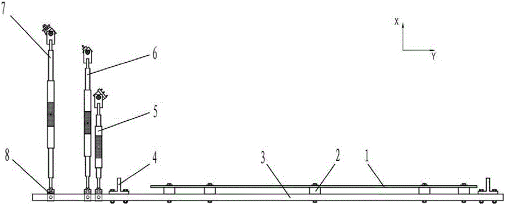
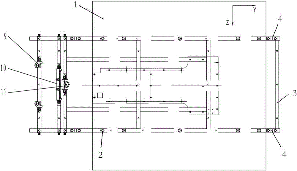
[0031] see attached figure 1 , 2 , the XYZ coordinate system in the figure is based on the direction of the drawing, which is convenient for the description in this manual. The supporting device of the antenna deployment is mainly composed of the analog board 1, the heat insulation connection component 2, the support beam frame 3, the lifting lug 4, the lower support rod component 5, the middle support rod component 6, the upper support rod component 7, the heat insulation pad block 8, etc...


PUM


Abstract

The invention relates to the technical field of strut member steel structures and provides a supporting device used for satellite antenna deployment. The device comprises a supporting beam frame and a breadboard, wherein the supporting beam frame is of a rectangular frame structure, the breadboard is arranged at a position close to the rear end of the frame structure of the supporting beam frame, the breadboard is wider than the supporting beam frame and is shorter than the supporting beam frame, a plurality of lifting lugs are further arranged on the supporting beam frame, a first transverse plate, a second transverse plate and a third transverse plate are arranged at the front end of the supporting beam frame in sequence, an upper antenna connecting plate, a middle antenna connecting plate and a lower antenna connecting plate are arranged on the three transverse plates, an upper supporting rod component, a middle supporting rod component and a lower supporting rod component are arranged on the three antenna connecting plates, the upper supporting rod component is longer than the middle supporting rod component, and the middle supporting rod component is longer than the lower supporting rod component. According to the supporting device used for satellite antenna deployment, antennae and a corresponding mechanism are supported and fixed after being deployed according to specific angles, and gravity unloading is achieved.

Description

technical field [0001] The present invention relates to the technical field of steel structures for supporting parts, in particular to a supporting device for deploying satellite antennas. Background technique [0002] Satellite antennas are important equipment for satellites and are used outside the satellite cabin. In order to meet the temperature requirements of the space environment, corresponding thermal control measures are required. Therefore, the antenna needs to perform thermal vacuum and thermal balance tests on the ground to verify the correctness of the antenna thermal control design. performance, effectiveness, and the ability of the antenna to adapt to the space environment. [0003] The antenna of each satellite has different structures due to different functions. It is generally composed of a mechanism mounting plate, an unfolding arm, a two-dimensional pointing mechanism, an antenna, etc. The antenna is generally kept in a retracted state during transportati...

Claims


Application Information

Patent Timeline
Patent Type & Authority Patents(China)
IPC IPC(8): H01Q1/08H01Q1/12
Inventor 李灿伦景加荣彭光东陈丽王飞朱小标
Owner SHANGHAI INST OF SATELLITE EQUIP
Learn More