A fabry-perot etalon calibration system and method for long-term optical frequency compensation of scanning cavity

A frequency compensation and etalon technology, applied in radio wave measurement systems, electromagnetic wave re-radiation, utilization of re-radiation, etc., can solve the problems of slowness, transmittance curve error, slow scanning speed, etc.

Inactive Publication Date: 2015-10-21
UNIV OF SCI & TECH OF CHINA
View PDF6 Cites 0 Cited by
  • Summary
  • Abstract
  • Description
  • Claims
  • Application Information

AI Technical Summary

Problems solved by technology

[0006] The existing three calibration methods for the etalon have the following disadvantages: the method of scanning the cavity length of the etalon, during the scanning process, due to the frequency drift of the laser incident into the etalon, this frequency drift will directly cause the scanned transmission Errors occur in the overrate curve; the method of scanning the refractive index needs to pressurize or decompress the cavity of the etalon during the scanning process, which is a slow process, so the scanning speed is very slow; the method of scanning the laser output frequency of the laser, due to It is also necessary to add another laser as a reference light to beat the outgoing laser to detect and stabilize the laser frequency. Therefore, complex optical path structures, optical devices and frequency stabilization methods are required to stabilize the laser frequency so that the laser frequency incident into the etalon The error caused by the jitter is controlled within an acceptable range

Method used


Image

  • A fabry-perot etalon calibration system and method for long-term optical frequency compensation of scanning cavity
  • A fabry-perot etalon calibration system and method for long-term optical frequency compensation of scanning cavity
  • A fabry-perot etalon calibration system and method for long-term optical frequency compensation of scanning cavity

Examples


Embodiment Construction

[0021] In order to make the object, technical solution and advantages of the present invention clearer, the present invention will be further described in detail below in conjunction with specific embodiments and with reference to the accompanying drawings.

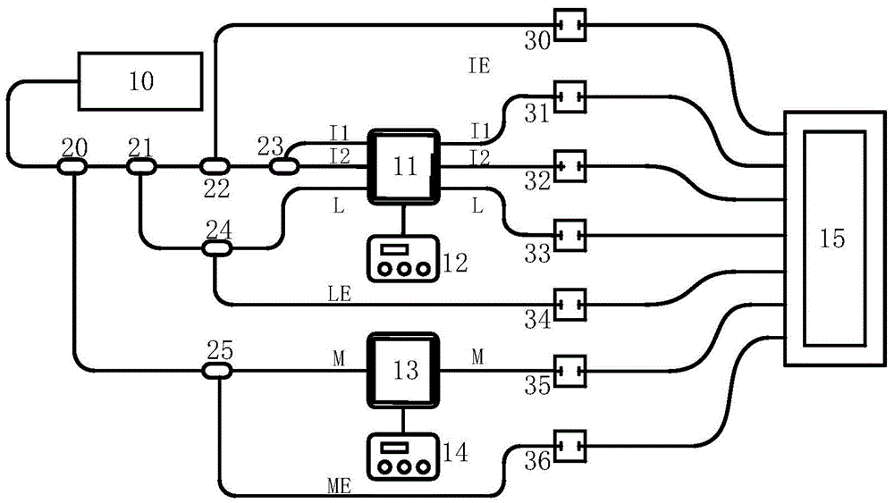
[0022] figure 1 A system schematic diagram of one embodiment of the invention is shown. The operating wavelength of the system is located at 355nm. The system includes a laser 10, a first Fabry-Perot etalon 11, a first etalon controller 12, a second Fabry-Perot etalon 13, a second etalon controller 14, an oscilloscope 15, a first fiber splitter 20, The second optical fiber splitter 21, the third optical fiber splitter 22, the fourth optical fiber splitter 23, the fifth optical fiber splitter 24, the sixth optical fiber splitter 25, the first detector 30, the second detector 31 , a third detector 32 , a fourth detector 33 , a fifth detector 34 , a sixth detector 35 , and a seventh detector 36 . The first Fabry-Perot eta...


PUM


Abstract

The invention provides a Fabry-Perot etalon-calibrating system and a Fabry-Perot etalon-calibrating method for carrying out optical frequency compensation at cavity length scanning. The system is established on the basis of a dual-edge direct-detecting wind-measuring laser-radar system with the operating wavelength of 355nm, the drift of laser frequency which is irradiated into the other Fabry-Perot etalon is monitored in real time by using the Fabry-Perot etalon with fixed cavity length when the transmittance of one Fabry-Perot etalon is scanned, the frequency abscissa of a transmittance curve which is obtained through scanning is corrected by utilizing the obtained laser-frequency drift through monitoring, so that the more accurate transmittance curve is obtained, calibration errors brought by the drift of incident laser frequency are eliminated, a more accurate frequency response function can be further obtained, and wind-speed errors are reduced. Through the Fabry-Perot etalon-calibrating system and the Fabry-Perot etalon-calibrating method, the problem of system errors brought by laser-frequency instability caused by the large-temperature-difference and strong-vibration environments of vehicle-mounted laser radars is effectively solved.

Description

technical field [0001] The invention belongs to the technical field of direct detection wind laser radar, and in particular relates to a Fabry-Perot etalon calibration system and method for long-term optical frequency compensation of a scanning cavity. Background technique [0002] The Doppler wind lidar technology based on Rayleigh scattering is the only laser remote sensing method for the middle and upper atmosphere. The basis of this wind measurement method is to obtain the accurate transmittance curve of the Fabry-Perot discriminator, so as to complete the calibration of the Fabry-Perot etalon. The existing scanning transmittance methods are as follows: [0003] The direct detection Doppler lidar of the University of Science and Technology of China uses the method of changing the etalon cavity length to scan the transmittance curve during the calibration process, so as to achieve the purpose of calibration. Depend on (where δ is the optical path difference, n is the ...

Claims


Application Information

Patent Timeline
Patent Type & Authority Patents(China)
IPC IPC(8): G01S7/497
CPCG01S7/497G01S17/95
Inventor 赵若灿窦贤康上官明佳韩於利夏海云孙东松
Owner UNIV OF SCI & TECH OF CHINA
Why Eureka
Try Eureka