Sliding bearing and method to perform service at sliding bearing

A sliding bearing and bearing technology, applied in sliding contact bearings, bearing maintenance/replacement, shaft maintenance/replacement, etc., to save maintenance time and reduce possibility

Active Publication Date: 2014-03-26
SIEMENS GAMESA RENEWABLE ENERGY AS
View PDF3 Cites 15 Cited by
  • Summary
  • Abstract
  • Description
  • Claims
  • Application Information

AI Technical Summary

Problems solved by technology

There is also the problem of dust and foreign particles, which can get into an open bearing during servicing and become insidiously lodged within the bearing when the servicing is concluded and the bearing is closed again

Method used


Image

  • Sliding bearing and method to perform service at sliding bearing
  • Sliding bearing and method to perform service at sliding bearing
  • Sliding bearing and method to perform service at sliding bearing

Examples


Embodiment Construction

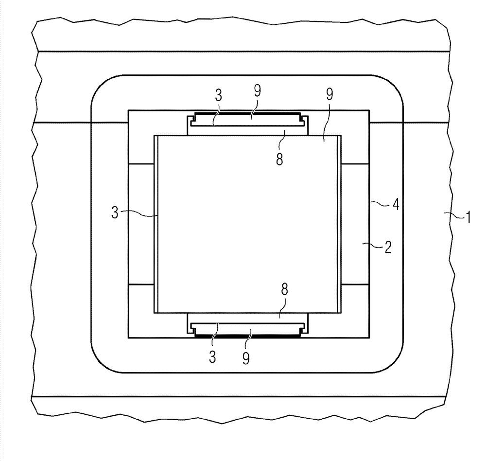
[0078] figure 1 A slide bearing with openings is shown.

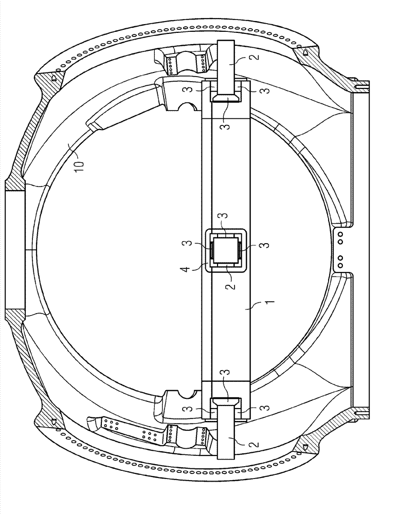
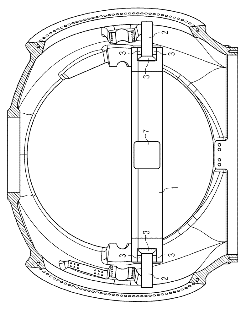
[0079] figure 1 A cut through a plain bearing of a hub 10 of a wind turbine is shown. The bearing includes a first bearing shell 1 and a second bearing shell 2 . The second bearing shell 2 is attached to the hub 10 of the wind turbine. The second bearing shell 2 rotates together with the hub 10 of the wind turbine and is thus a rotatable part of the bearing.

[0080] The first bearing shell 1 is attached to a stationary part of the wind turbine (not shown) and is thus the stationary part of the bearing.

[0081] A plurality of bearing pads 3 are provided between the first bearing shell 1 and the second bearing shell 2 .

[0082] The first bearing shell 1 comprises an opening 4 . The bearing pad 3 is visible through this opening 4 .

[0083] The location of the opening 4 is at a location with good accessibility eg during maintenance of the wind turbine. The position of the opening 4 can also be chosen so as to be...


PUM


Abstract

The invention relates to a sliding bearing and a service method to perform a service at a sliding bearing. A sliding bearing comprises a first bearing shell 1 and a second bearing shell 2 and a plurality of bearing pads 3 arranged between first and the second bearing shell. In addition the bearing comprises an opening 4 in the first bearing shell 1, whereby the opening 4 is arranged in a way that the bearing pads 3 are visible through the opening 4.

Description

technical field [0001] The invention relates to a sliding bearing and a maintenance method for performing maintenance at the sliding bearing. Background technique [0002] Wind turbines convert the energy of moving air into electricity. The moving air accelerates the wind turbine's rotor. The rotation of the rotor is transmitted to the generator. Generators convert rotational energy into electrical energy. [0003] In recent years, the concept of direct drive wind turbines has been established. In a direct drive wind turbine, the rotational energy of the rotor is transferred directly to the generator without the use of a gearbox. [0004] In a direct drive wind turbine, the rotor of the wind turbine is directly connected to the rotor of the generator. The chain of mechanically connected parts from the rotor of the wind turbine to the rotor of the generator is called the drive train of the wind turbine. [0005] In order to allow rotational movement and to provide the n...

Claims


Application Information

Patent Timeline
Patent Type & Authority Applications(China)
IPC IPC(8): F03D11/00F16C33/04
CPCF16C2237/00F16C17/03F16C2300/14F16C2360/31F05B2240/50F03D80/70F16C19/525Y10T29/49638Y02E10/72F16C43/02
Inventor B.彼得森K.汤森
Owner SIEMENS GAMESA RENEWABLE ENERGY AS
Why Eureka
Try Eureka