
Full Face Shaft Drilling Rig

A full-section, drilling rig technology, applied in shaft equipment, sinking, earthwork drilling, etc., can solve problems such as difficulty in automation of sinking equipment, difficulty in increasing the speed of shaft excavation, and failure to achieve major breakthroughs, so as to shorten the construction of wells cycle, easy to operate and use, and a high degree of mechanical automation

Active Publication Date: 2016-03-23
CHINA RAILWAY ENGINEERING EQUIPMENT GROUP CO LTD
View PDF5 Cites 0 Cited by
  • Summary
  • Abstract
  • Description
  • Claims
  • Application Information

AI Technical Summary

Problems solved by technology

Shaft drilling equipment has also experienced the same development process. The equipment technology has matured, but no major breakthrough has been achieved. The traditional construction method is still used, and it is difficult to automate the drilling equipment, parallel construction is difficult, the drilling efficiency is low, and the labor intensity of personnel is high. Big
my country's existing shaft excavation equipment technology has been developed and matured after many improvements, but it is difficult to increase the shaft excavation speed only by improving the construction efficiency of a single equipment

Method used


Image

  • Full Face Shaft Drilling Rig
  • Full Face Shaft Drilling Rig
  • Full Face Shaft Drilling Rig

Examples


Embodiment 1

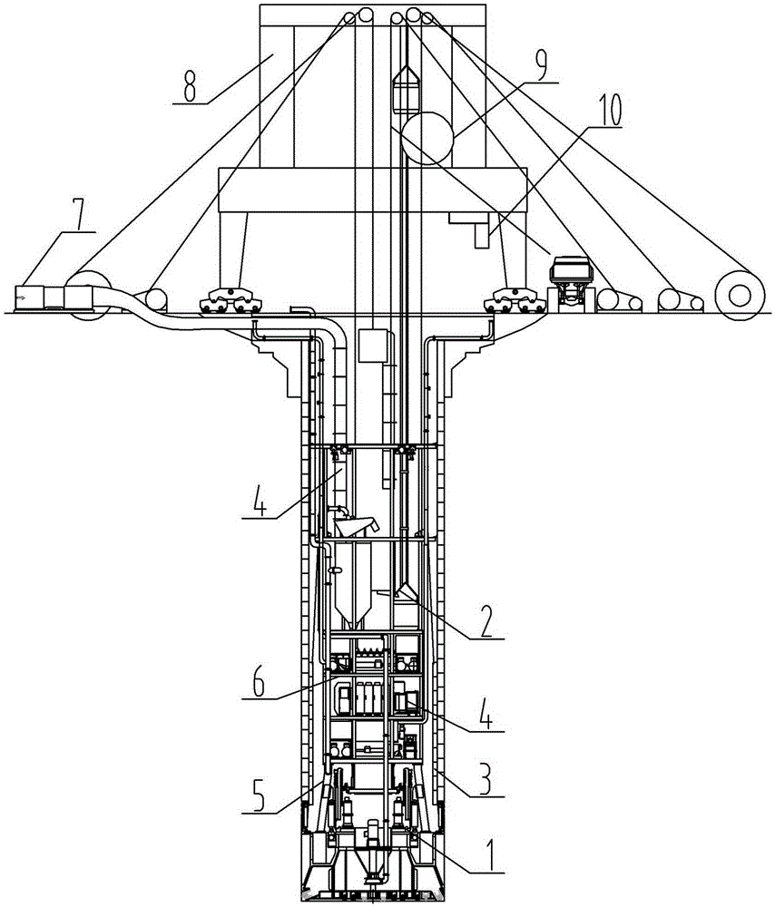
[0034] see Figure 1 to Figure 8 , in the figure, the full-section vertical shaft drilling rig of the present invention is divided into four major systems and equipment main beam 5, equipment platform 6, fan 7. Derrick 8, cable drum 9, control room 10, etc. Each system is composed of independent equipment.

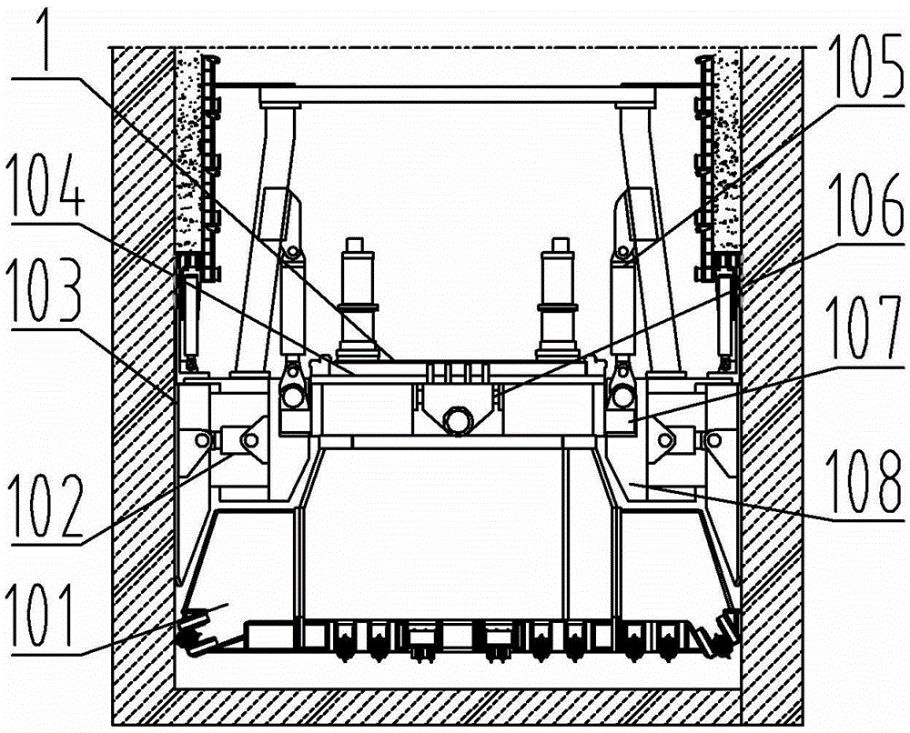
[0035] The shaft excavation system is mainly composed of a cutter head 101, a shoe cylinder 102, a shoe 103, a main drive 104, a propulsion cylinder 105, a steering knuckle 106, a cross shaft 107, and a shoe fixed ring 108. There are multiple stretchers and form an annular structure, and each stretcher is connected to the main drive through a sliding key. The stretcher cylinder 102 tightens the stretcher 103 and acts on the well wall to generate the force point of the propulsion cylinder 105. The propulsion cylinder pushes 105 to push the main drive 104 and then pushes the cutterhead 101 to generate excavation action. The cutterhead 101 is controlled by controlling the ex...


PUM


Abstract

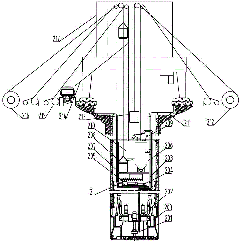
The invention belongs to the technical field of mineral product machinery and discloses a full-fracture-surface vertical shaft drilling machine which comprises a device main girder, device platforms, a head frame, a tunneling system, a personnel and material conveying system, a shaft wall supporting and protecting system, a guaranteeing system and a manipulating chamber. The tunneling system is installed at the front end of the device main girder, the device platforms are installed at the rear end of the device main girder, the head frame is arranged on a shaft mouth, the manipulating chamber is arranged on the head frame, the personnel and material conveying system and the guaranteeing system are installed on the rear portion of the tunneling system, the shaft wall supporting and protecting system is arranged on the rear portion of the tunneling system and the periphery of the tunneling system, the personnel and material conveying system comprises a hoister, a first-level separation station, a slag storage cabin, a second-level separation station, a feeding mechanism and a conveying pump, the shaft wall supporting and protecting system comprises an auxiliary crane, a hoister, an underground concrete mixing tank, a concrete pump and an anchoring system, and the auxiliary crane, the hoister, the underground concrete mixing tank, the concrete pump and the anchoring system are installed on the device platforms respectively. The full-fracture-surface vertical shaft drilling machine solves the construction problems of large-scale vertical shafts such as coal mines, complete equipment of automation, mechanization and integration of the functions of shaft tunneling, slag tapping, supporting, protection, water discharging, ventilation and the like, the construction efficiency is improved, the construction cost is reduced, the construction safety is improved, and the application range is wide.

Description

technical field [0001] The invention belongs to the technical field of mining machinery, in particular to a full-face shaft drilling machine. Background technique [0002] The existing shaft excavation methods have undergone long-term development. The main drilling methods include drill and blast method and drilling method, and the construction technology has been mature. Shaft drilling equipment has also experienced the same development process. The equipment technology has matured, but no major breakthrough has been achieved. The traditional construction method is still used, and it is difficult to automate the drilling equipment, parallel construction is difficult, the drilling efficiency is low, and the labor intensity of personnel is high. Big. The existing shaft excavation equipment technology in our country has been developed and matured after several improvements, but it is difficult to increase the shaft excavation speed only by improving the construction efficienc...

Claims


Application Information

Patent Timeline
Patent Type & Authority Patents(China)
IPC IPC(8): E21D1/06E21D1/08E21D5/04E21D7/00
Inventor 李建斌赵华张宁川肖威卓兴建王杜娟贾连辉蒲晓波董艳萍郑永光王双旺周倩
Owner CHINA RAILWAY ENGINEERING EQUIPMENT GROUP CO LTD
Learn More