
Beam and stand column connecting structure

A technology for connecting structures and beams, applied in building components, building structures, earthquake resistance, etc., can solve the problems of low seismic capacity and small bearing capacity, and achieve the effect of increasing bearing capacity and enhancing seismic capacity.

Inactive Publication Date: 2014-03-26
CHONGQING CHENGSHUO TECH
View PDF0 Cites 0 Cited by
  • Summary
  • Abstract
  • Description
  • Claims
  • Application Information

AI Technical Summary

Problems solved by technology

[0004] The technical problem to be solved by the present invention is to provide a connection structure between beams and columns to solve the problems of low bearing capacity and low earthquake resistance of prefabricated beams in existing building construction

Method used


Image

  • Beam and stand column connecting structure
  • Beam and stand column connecting structure

Examples


Embodiment Construction

[0012] Below in conjunction with accompanying drawing and specific embodiment the present invention will be described in further detail:

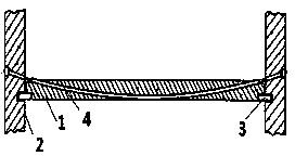
[0013] Such as figure 1 , figure 2 The connection structure of the beam and the column shown includes a beam 1, two columns 2, a hinge 3 and a tension rope 4, and the two ends of the beam 1 are respectively hinged with the two columns 2 through the hinge 3, and the tension rope 4 is along the The longitudinal direction of the crossbeam 1 passes through the inside of the crossbeam 1 , and the two ends of the tension rope 4 protrude from the crossbeam 1 and are respectively connected with two columns 2 .

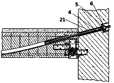
[0014] The more specific connection mode between the end of the tension rope 4 and the column 2 is as follows: a tubular channel 21 for the tension rope to pass is provided inside the column 2 along the radial direction of the column, and a hole is provided at the end of the channel 21. An end plate 4 through which the tensioning rope 4 ...


PUM


Abstract

The invention discloses a beam and stand column connecting structure which is used in construction for solving the problems that in the prior art, a prefabricated beam is low in bearing capacity and shock resistance. The beam and stand column connecting structure comprises a beam and stand columns. The two ends of the beam are hinged to the two stand columns respectively. The beam and stand column connecting structure is characterized in that the beam and stand column connecting structure further comprises a tensioning rope, the tensioning rope penetrates through the beam in the length direction of the beam, and the two ends of the tensioning rope extend out of the beam and are connected with the two stand columns respectively. The tensioning rope serves as an auxiliary reinforcing structure, the bearing capacity of the beam can be improved, the shock resistance of the beam can also be improved, and the beam and stand column connecting structure does not occupy extra space and does not influence construction.

Description

technical field [0001] The invention relates to a connection structure used in building construction, in particular to a connection structure of a beam and a column. Background technique [0002] As we all know, building construction methods using prefabricated concrete components have become more and more common in recent years. However, since modern buildings are mostly used for commercial and residential buildings, especially these buildings are mostly high-rise buildings, there are many problems in modern building construction that need to be solved. [0003] At present, the prefabricated beams used in building construction have the disadvantages of low bearing capacity and low earthquake resistance because they are only connected to columns at both ends without other auxiliary reinforcement structures. Contents of the invention [0004] The technical problem to be solved by the present invention is to provide a connection structure between beams and columns, so as ...

Claims


Application Information

Patent Timeline
IPC IPC(8): E04B1/18E04B1/22E04B1/98
Inventor 李清芬
Owner CHONGQING CHENGSHUO TECH
Learn More