
Flow distributing facility of front water feeding pond of large circulating water pump station of power plant and construction method for flow distributing facility

A technology of circulating water pump and forecourt, used in pumping stations, water conservancy projects, water conservancy engineering equipment, etc., can solve the problems of increasing project investment and floor space, unsatisfactory rectification effect, affecting the safe operation of pumps, etc. Excellent effect, shortening the length of the front pool, and easy construction

Active Publication Date: 2014-03-26
ZHEJIANG ELECTRIC POWER DESIGN INST
View PDF4 Cites 6 Cited by
  • Summary
  • Abstract
  • Description
  • Claims
  • Application Information

AI Technical Summary

Problems solved by technology

If it is arranged according to the conventional plan 2 rectification method, the minimum length of the forebay needs to be 14.0m, and the total length of the underground structure of the whole pumping station will reach 51.40m, which also exceeds the allowable length of the underground reinforced concrete structure as a whole design, and also increases the project investment. and the rectification effect is unsatisfactory, which can easily cause the occurrence of vortex in the pump suction well and affect the safe operation of the pump

Method used


Image

  • Flow distributing facility of front water feeding pond of large circulating water pump station of power plant and construction method for flow distributing facility
  • Flow distributing facility of front water feeding pond of large circulating water pump station of power plant and construction method for flow distributing facility

Examples


Embodiment

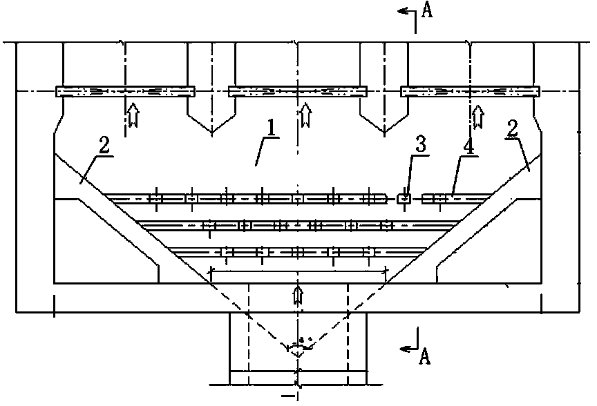
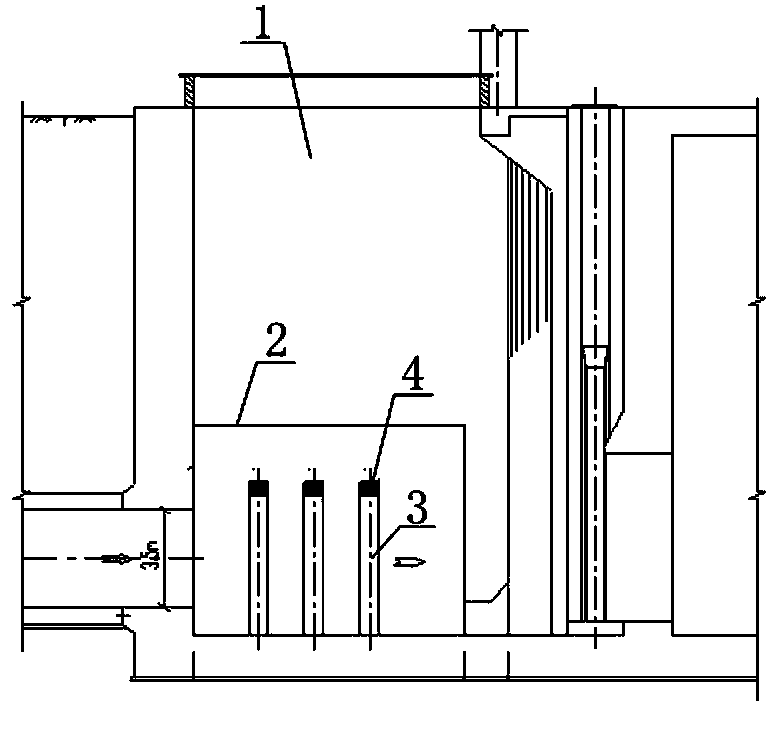
[0027] Embodiment: The present invention first determines the wing walls on both sides according to the width and depth of the water diversion tunnel (or open channel) of the pumping station and the water inlet forebay, and sets reinforced concrete rectifying square columns between the tunnel (or open channel) entrance and the wing walls on both sides Three rows, arranged in a plum blossom shape, the first row is 1.7-2.0m away from the entrance of the tunnel (or open channel), and the distance between each row is ~1.5m. The scale of water diversion and the size of the water inlet pool are changed to adjust the distance between columns and columns, and between rows; flush). In this way, the distance from the exit of the tunnel to the entrance of the flow path of the pumping station is 8.50m, and the total length of the underground structure of the pumping station is 45.90m.

[0028] The present invention firstly solves the problem of effective rectification of the inlet foreba...


PUM

PropertyMeasurementUnit
Angleaaaaaaaaaa

Abstract

The invention provides a flow distributing facility of a front water feeding pond of a large circulating water pump station of a power plant and a construction method for the flow distributing facility. The flow distributing facility comprises the front water feeding pond, wherein flow guiding wing walls which form an included angle of 60-90 degrees are respectively casted on two sides of the front water feeding pond; rows of flow distributing columns which are transversely arranged are arranged in the front water feeding pond and between the two flow guiding wing walls along the water feeding direction at least; each row of flow distributing columns consists of a plurality of square columns; the square columns of one row of flow distributing columns and the square columns of the adjacent rows of flow distributing columns are arranged in a staggered manner; the number of the square columns of each row of flow distributing columns is progressively increased along the water flow direction; and cross beams which are connected with the flow guiding wing walls on the two sides of the front water feeding pond are arranged on tops of the flow distributing columns. The construction method comprises the following steps of (a) constructing the flow distributing facility and a main body structure of an underground portion of the pump station together, and constructing the front water feeding pond of the pump station at first; (b) reserving anchor bars for casting the flow guiding wing walls according to two sides of the front water feeding pond and a bottom plate, and casting the flow guiding wing walls on the two sides of the front water feeding pond; (c) casting flow distributing square columns and forming the rows of flow distributing columns according to the anchor bars reserved on the bottom of the front water feeding pond after the flow guiding wing walls on the two sides of the front water feeding pond are constructed; and (d) casting the cross beams on the tops of the flow distributing columns, and connecting the cross beams and the flow guiding wing walls on the two sides of the front water feeding pond.

Description

technical field [0001] The invention relates to a seaside power plant, including a water flow rectification method for a forebay of circulating water pumping stations for coal, fuel oil, gas, nuclear power, etc., and belongs to the technical field of power plants. Background technique [0002] At present, the construction of power plants and nuclear power plants in our country is developing in the direction of high parameters and large capacity, in order to achieve energy saving and consumption reduction, and meet the demand for electricity for economic development. However, the cooling water flow of circulating water in large thermal power plants and nuclear power plants is very large. Considering the convenience of water intake and drainage, the economical operation of the unit, as well as land saving and environmental protection, many large thermal power plants and nuclear power plants are generally arranged in Seaside, and use open sea water for direct cooling of circula...

Claims


Application Information

Patent Timeline
IPC IPC(8): E02B1/00E03B5/00
Inventor 邱纪龙吴建国沈又幸钱海平李琪艾月平韩建民钱锋曾上将陈开耀
Owner ZHEJIANG ELECTRIC POWER DESIGN INST
Learn More