
Knife

A technology of knives and blades, which is applied in the field of knives and can solve problems such as spring elongation and damage

Active Publication Date: 2014-03-26
MARTOR
View PDF4 Cites 1 Cited by
  • Summary
  • Abstract
  • Description
  • Claims
  • Application Information

AI Technical Summary

Problems solved by technology

In this respect, the spring is often stretched and thus damaged

Method used


Image

  • Knife
  • Knife
  • Knife

Examples


Embodiment Construction

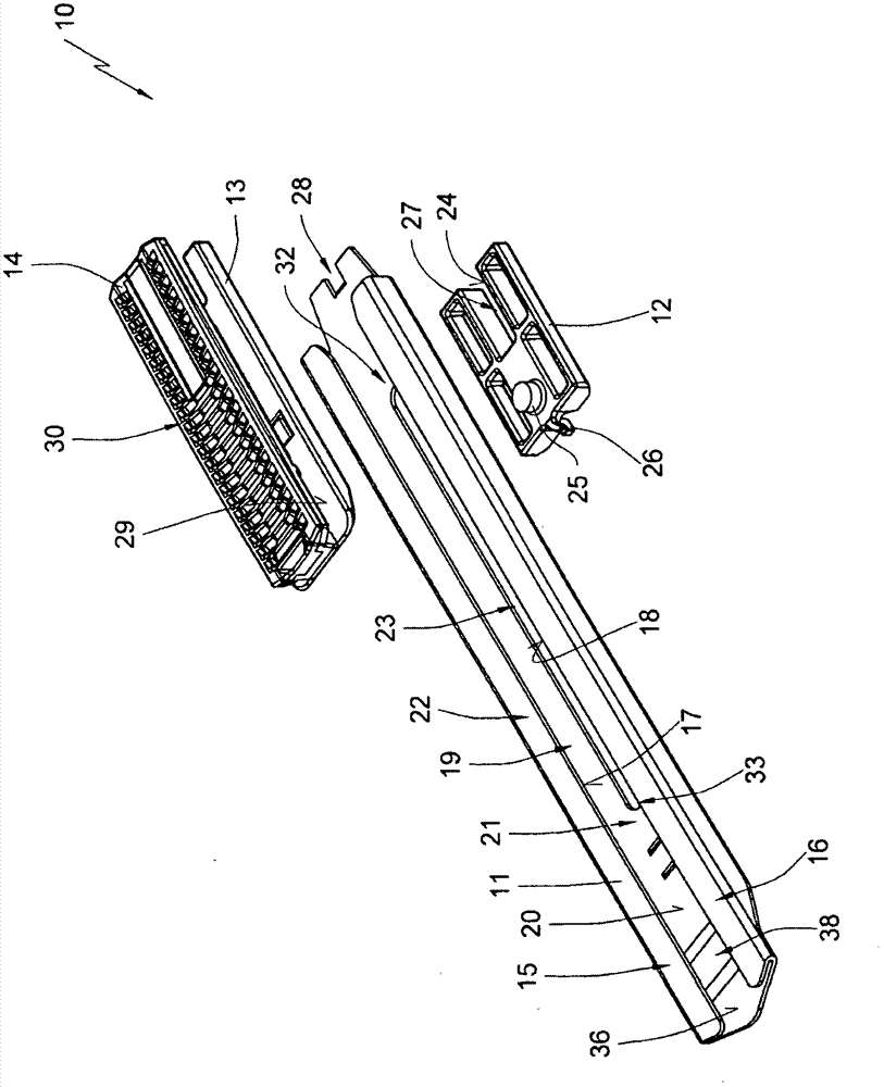
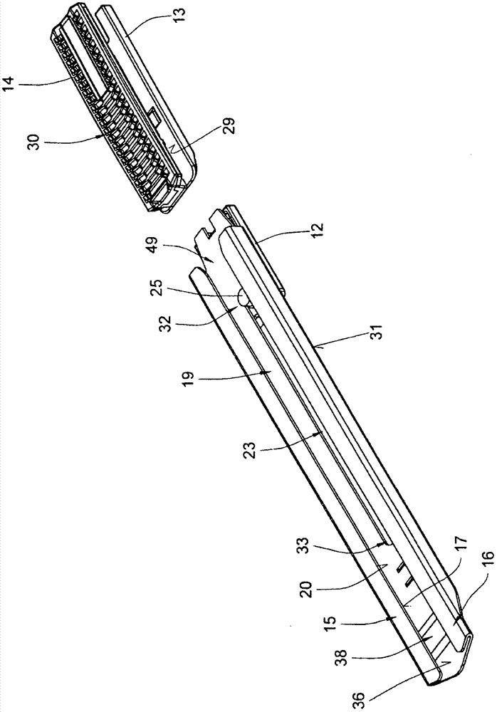
[0030] in accordance with figure 1 , The tool 10 includes a guide 11 , a spring slide 12 , a blade holder 13 and an operating device 14 .

[0031] The guide 11 is formed in the present embodiment from a sheet metal part. On the guide element 11 are side regions 15 and 16 which are bent and whose end faces 17 and 18 face each other and form guide surfaces. A groove 19 is formed between the end faces 17 and 18 . The base 20 is formed on a side wall 21 of the guide 11 . Side wall 21 is opposite side wall 22 formed by side regions 15 and 16 . figure 1 A blade, not shown in FIG. 1 , is guided between the face 20 and the side regions 15 and 16 . A slot 23 is formed in the wall 21 . In the rear region of the guide part 11, the tongue is freely cut and bent. reed in figure 1 cannot be seen in .

[0032] The spring carriage 12 has a guide surface 24 . The spring slide 12 also includes a drive pin 25 and a fastening hook 26 . On the side opposite the guide surface 24 , the spr...


PUM


Abstract

This invention relates to a knife with a housing (11) and with an actuation mechanism (14) with which a knife holder (13) can be moved with a blade (47) in the housing (11) between at least one safety position and at least one cutting position, whereby the knife holder (13) is held under spring load (35). The special feature is that the spring (35) is connected to the housing (11) and to a first coupling element (25) and in that the knife holder (13) is assigned to a second coupling element (46) that can mesh with and be disengaged from the first coupling element (25), whereby a movement of the knife holder from the safety position into the cutting position can enable the first coupling element (25) to be driven by the second coupling element (46).

Description

technical field [0001] The invention relates to a knife. Background technique [0002] Such knives are known from published prior applications. It consists of a housing in which the cartridge is guided. The blade holder is movable between a safety position and a cutting position. In the safety position, the blade is arranged inaccessibly in the housing and in the cutting position the blade protrudes from the housing. The spring is fixed on the housing and the cartridge and loads the cartridge into eg a safe position. [0003] To allow blade replacement, the cartridge is usually removed from the housing. In this respect, the springs are often stretched and thus damaged. Contents of the invention [0004] The object of the present invention is to provide a knife in which the blade change can be carried out comfortably and damage to the spring is avoided. [0005] This object is achieved by a tool having the features of claim 1 . [0006] The tool according to the inve...

Claims


Application Information

Patent Timeline
Patent Type & Authority Applications(China)
IPC IPC(8): B26B5/00B26B1/08
CPCB26B5/003B26B1/08B26B5/002
Inventor F·泽格勒
Owner MARTOR
Learn More