
Side supporting device of working roll of cold rolling machine

A technology of side support and work roll, applied in the direction of back pressure device, metal rolling, metal rolling, etc., can solve the problems of complex processing of rack and roll system, small rolling mill space, low unit output, etc. and surface quality, stable rolling process, and the effect of maintaining the rolling state

Active Publication Date: 2015-06-24
DALIAN DESIGN INST CO LTD CHINA FIRST HEAVY IND +1
View PDF6 Cites 0 Cited by
  • Summary
  • Abstract
  • Description
  • Claims
  • Application Information

AI Technical Summary

Problems solved by technology

However, the shortcomings of the 20-high rolling mill are: the processing of the frame and the roll system is complicated, the space in the rolling mill is small, the lubrication of the roll system is difficult, the strip steel to be rolled cannot be too wide, the rolling speed cannot be too high, the output of the unit is low, and it cannot be widely used. application
If the working rolls of the six-high rolling mill are reduced enough to roll ultra-thin and super-hard strips, the front and rear tension of the strips will cause the small-diameter working rolls to bend in the horizontal direction, which will seriously affect the rolling of the final finished strip. plate shape, plate thickness and surface quality

Method used


Image

  • Side supporting device of working roll of cold rolling machine
  • Side supporting device of working roll of cold rolling machine
  • Side supporting device of working roll of cold rolling machine

Examples


Embodiment Construction

[0016] The present invention will be further described below in conjunction with the drawings and embodiments.

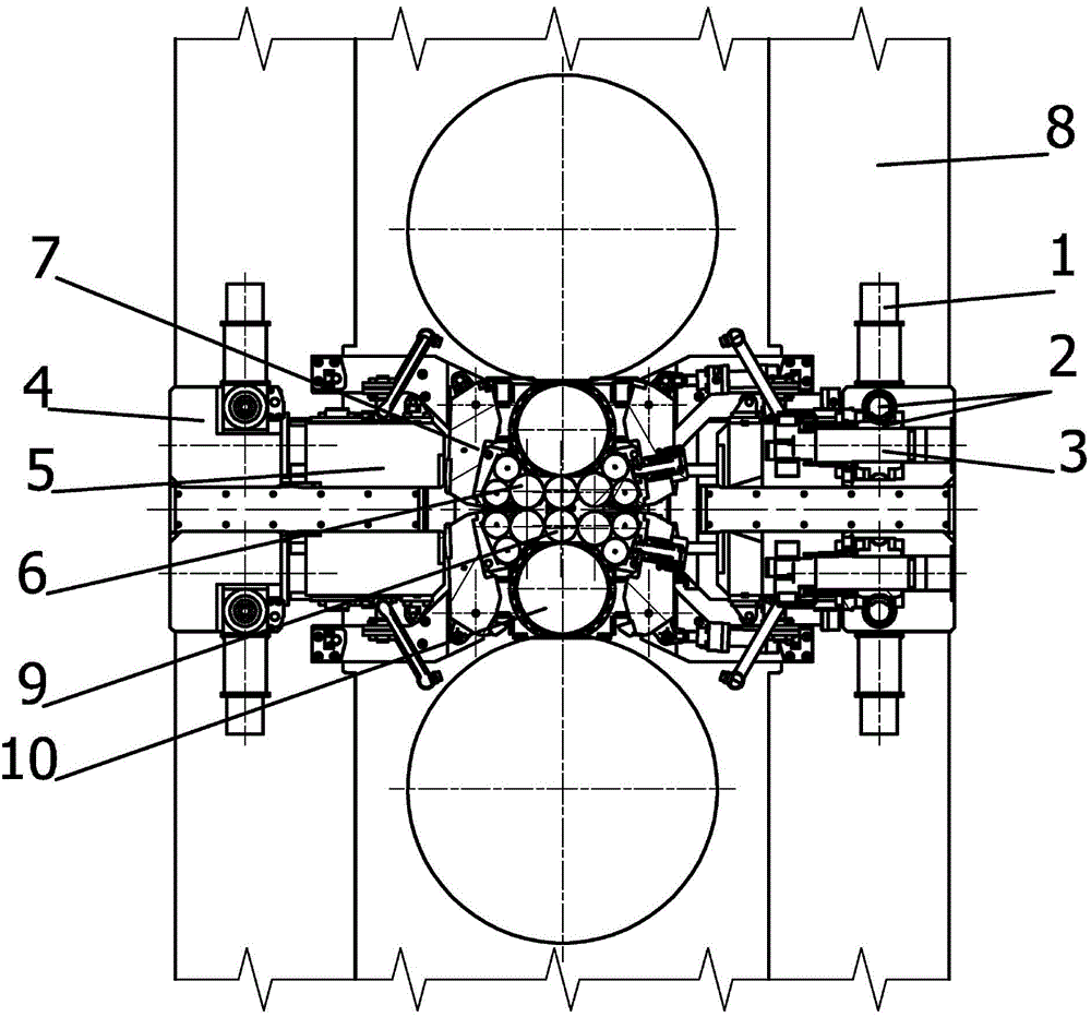
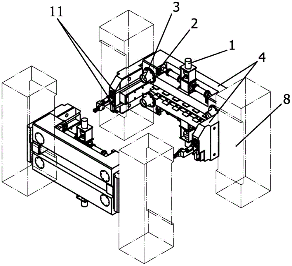
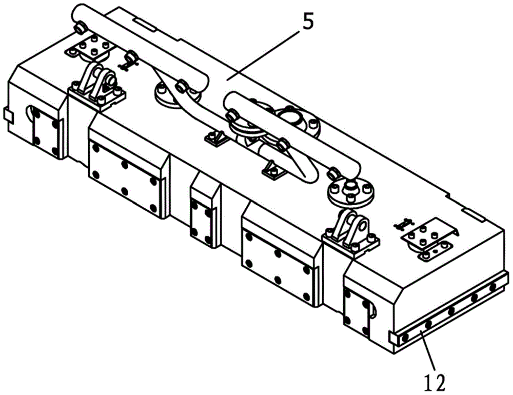
[0017] The specific embodiment of the present invention is shown in the drawings. The device includes a fixing device 4, a moving device 5, a side support roller swing lever device 7 and a side support roller system 6. The fixing device 4 includes a channel steel frame, an oil motor 1, a worm gear For mechanism 2 and screw mechanism 3, two transverse slide grooves 11 are arranged in the middle of the two wall plates of the channel steel frame. Two oil motors 1 are installed on the bottom plate of the channel steel frame, respectively located in the middle of the two sides of the bottom plate. The worm gear mechanism 2 is installed on the bottom plate of the channel steel frame, respectively located at the four corners of the bottom plate. The input ends of the two worm gear mechanisms 2 mounted on the channel steel frame bottom plate and the oil installed in the middle ...


PUM


Abstract

The invention discloses a side supporting device of a working roll of a cold rolling machine. The side supporting device comprises a fixed device, a moving device, side-supporting roll swinging rod devices and side supporting roll systems, wherein oil motors, worm gear mechanisms and lead screw mechanisms are arranged on the fixed device which is provided with horizontal sliding grooves; the moving device is provided with thread holes matched with the lead screw mechanisms and sliding keys matched with the sliding grooves of the fixed device; each swinging rod device comprises two fixed arms, a swinging beam and two hydraulic cylinders; the two fixed arms of each swinging rod device are fixedly arranged at the inner side of a bending-roll moving block of a middle roll; the bending-roll moving block moves up and down along a bending roll fixed block which is fastened on a rack of the rolling machine; each side supporting roll system comprises two supporting seats, a side supporting roll and two rows of backlining rolls; the side supporting roll systems are fixed on the swinging beams of the swinging rod devices. The side supporting device disclosed by the invention has the beneficial effects that when ultrathin and ultrahard cold-rolled strip steel is rolled, the working roll can be prevented from bending in the horizontal direction, the rolling state is stable, the structure of the device is simple and novel, and the rolled product is good in quality.

Description

Technical field [0001] The invention belongs to the technical field of metallurgical machinery, and particularly relates to a work roll side supporting device of a cold rolling mill. Background technique [0002] The domestic common carbon steel strip rolling is mainly based on the six-high cold rolling mill, but due to the large diameter of the work roll of the six-high cold rolling mill, it cannot meet the rolling requirements of ultra-thin strip, silicon steel and stainless steel. For extremely thin strip, silicon steel and stainless steel rolling, most of them are rolled by a 20-high rolling mill. The diameter of the work roll of the 20-high rolling mill is about Φ50, the contact area of ​​the deformation zone of the small roll diameter is small, the rolling force is reduced, and the ultra-thin, super-hard strip steel can be rolled. However, the disadvantages of the 20-high rolling mill are: complex processing of racks and rolls, small space in the rolling mill, difficult lu...

Claims


Application Information

Patent Timeline
Patent Type & Authority Patents(China)
IPC IPC(8): B21B29/00
Inventor 王斌宋智良孟文华张元健高成章蒋兴华李东方
Owner DALIAN DESIGN INST CO LTD CHINA FIRST HEAVY IND
Learn More