Control mechanism for index plunger

A technology of control mechanism and indexing pin, which is applied in the field of workpiece positioning device, to achieve the effect of avoiding improper force and convenient loading and unloading

Inactive Publication Date: 2014-03-19
CHONGQING BISHAN AIHUA
View PDF0 Cites 3 Cited by
  • Summary
  • Abstract
  • Description
  • Claims
  • Application Information

AI Technical Summary

Problems solved by technology

[0003] The present invention intends to provide an indexing pin control mechanism to solve the problem of realizing precise action control of the indexing pin in the prior art

Method used


Image

  • Control mechanism for index plunger

Examples


Embodiment 1

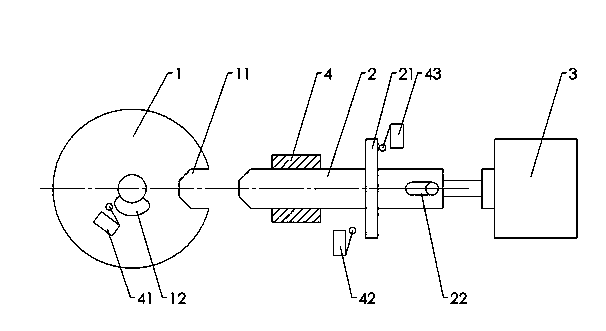
[0010] Embodiment one is basically as figure 1 As shown (part of the structure is not shown in the figure): the indexing pin is axially slidably connected in the frame, the spring connecting the indexing pin and the frame drives the indexing pin into the indexing plate, the front end of the indexing pin is in contact with the indexing The shape of the indexing hole on the dial matches, and the bar hole provided at the rear end of the indexing pin is hinged with the force-applying shaft of the solenoid valve, and the push-pull force generated by the solenoid valve drives the indexing pin to move axially.

[0011] The main shaft of the indexing plate is fixedly welded with a cam, and the middle part of the indexing pin is welded with a ring-shaped convex edge. When the indexing pin is inserted into the indexing hole, the indexing axis advance limit switch is closed, and when the indexing pin exits the indexing hole, the indexing shaft retreats. The limit switch is closed. When t...


PUM


Abstract

The invention discloses a control mechanism for an index plunger to solve the problem that control of precise action of the index plunger in the prior art cannot be achieved. The control mechanism for the index plunger comprises a frame, an index plate and the index plunger, wherein the index plate and the index plunger are matched to each other and positioned on a spindle, and a spring for driving the index plunger to be inserted into the index plate is arranged on the frame. The control mechanism for the index plunger is characterized in that a cam is arranged on the spindle, the index plunger goes in and out of an index hole in the index plate axially through a solenoid valve, a protruding edge is arranged in the middle of the index plunger, and a cam limit switch, an index shaft inserting limit switch and an index shaft retracting limit switch which are connected with the solenoid valve are arranged beside the curve surface of the cam and on the axial front side and the axial rear side of the protruding edge. The three switches are connected with a controller of the solenoid valve, inserting and retracting of the index plunger can be controlled through sensing of the three switches, the retreating of the index plunger is achieved through the solenoid valve, and the inserting of the index plunger is achieved through the spring.

Description

technical field [0001] The invention relates to a workpiece positioning device. Background technique [0002] The indexing head is a machine tool accessory installed on the milling machine to divide the workpiece into arbitrary equal parts. Using the indexing scale ring and vernier, the positioning pin and the indexing plate and the exchange gear, the indexing pin is inserted into the indexing under the action of the spring. The angle is fixed in the indexing hole of the disc, and the workpiece clamped between the centers or on the chuck can be divided into arbitrary angles, and the circumference can be divided into arbitrary equal parts. The auxiliary machine tool uses various shapes of tools to perform various grooves Processing of gears, helical spur gears, Archimedes helical cams, etc. It is also an important task of the indexing mechanism to realize the accurate action of the indexing pin. Contents of the invention [0003] The present invention intends to provide a...

Claims


Application Information

Patent Timeline
Patent Type & Authority Applications(China)
IPC IPC(8): B23Q16/06
CPCB23Q16/06
Inventor 姜静慧
Owner CHONGQING BISHAN AIHUA
Why Eureka
Try Eureka