Temperature control valve for floor heating return water

A valve and water technology, applied in the field of temperature control valves for household control, can solve the problems of high overall investment cost, short circuit of electronic equipment, cumbersome setting steps, etc., achieve good adjustment effect, improve control accuracy, and compact structure.

Active Publication Date: 2016-05-18
RIFENG ENTERPRISE FOSHAN CO LTD +2
View PDF6 Cites 0 Cited by
  • Summary
  • Abstract
  • Description
  • Claims
  • Application Information

AI Technical Summary

Problems solved by technology

This method can realize the automatic adjustment of the flow rate, but at the same time, there is also the problem of high cost. Since it is necessary to set up an electronic thermostat and an electric valve in each heating unit, the two need to be connected by electrician wiring. The steps are cumbersome, there is a risk of short circuit in the addition of electronic equipment on the water supply pipeline, and there are obvious safety hazards. start, the failure rate is high, and the sub-catchment controls the floor heating water in multiple rooms at the same time. The change of water volume in each room will cause fluctuations in water pressure. The floor needs to be heated before it can reach equilibrium with the room temperature. The adjustment of room temperature is often in a relatively lagging state, and often requires fluctuation adjustments many times to achieve temperature balance, resulting in energy loss, which is not conducive to energy saving

Method used


Image

  • Temperature control valve for floor heating return water
  • Temperature control valve for floor heating return water
  • Temperature control valve for floor heating return water

Examples


Embodiment

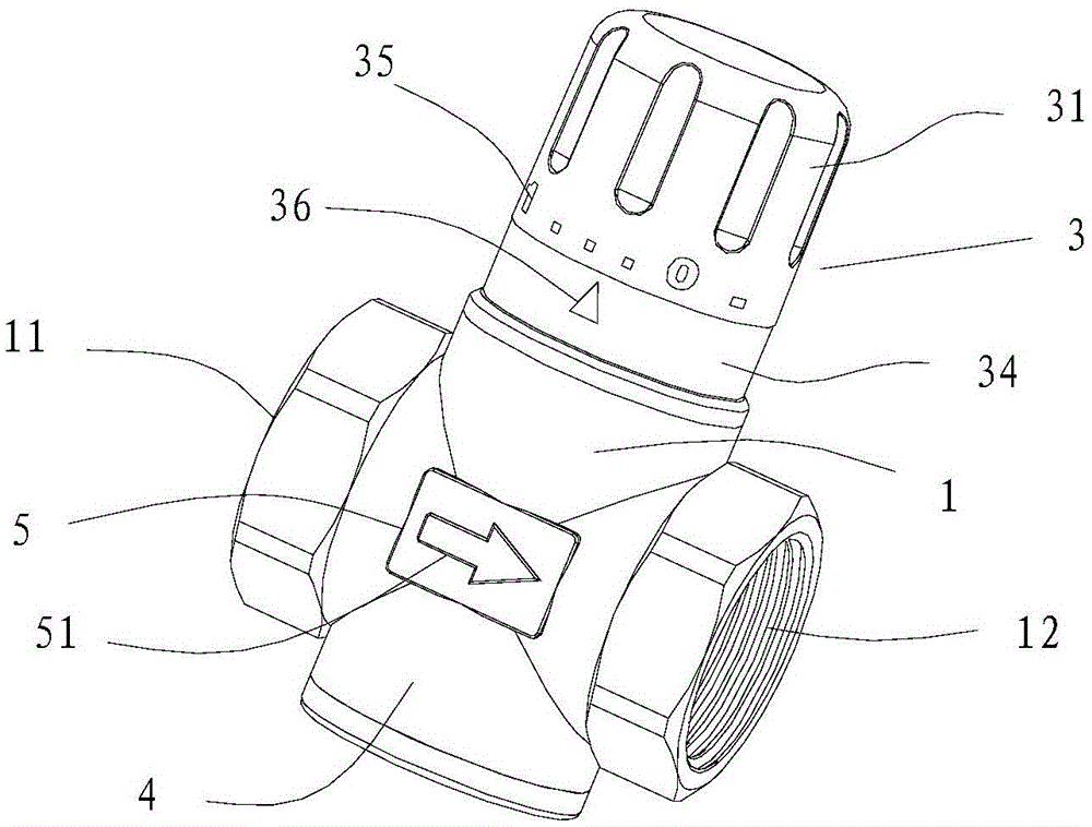
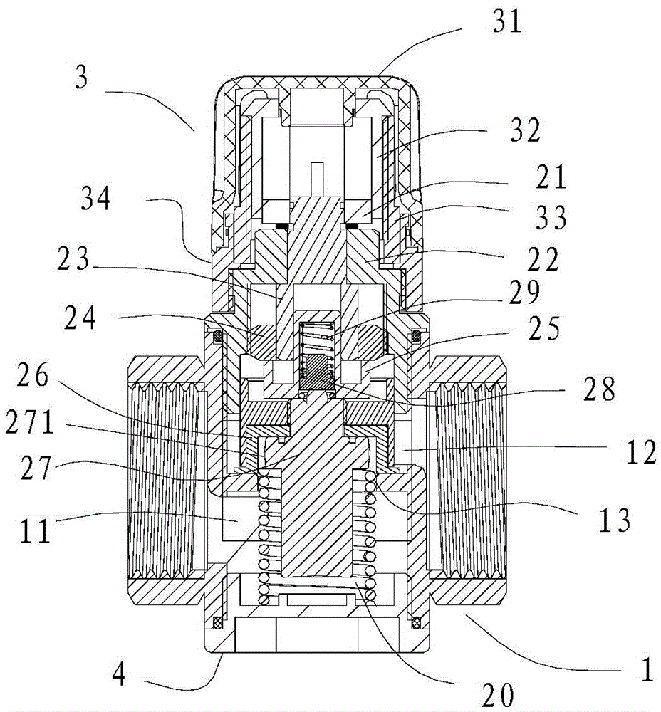
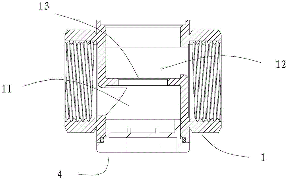
[0021] refer to Figure 1-5 , is a temperature control valve for floor heating and return water, including a valve body 1 with a first flow channel 11 and a second flow channel 12 inside, a temperature control valve core 2 set in the valve body 1, and a temperature adjustment handwheel 3 , sealing cover 4, wherein the valve body 1 is a cross-shaped straight-through structure, and a vertical through hole 13 is provided between the first flow channel 11 and the second flow channel 12 inside it, and the temperature control valve core 2 includes a valve body connected to the valve body 1 The spool cover 22 on the top, the valve stem assembly sleeved in the spool cover 22, the temperature sensing element 27 with a step portion 271 on the outer wall, and the first spring 20, the temperature sensing element 27 is vertically installed in the through hole 13, The stepped portion 271 thereof is located in the second circulation channel 12 above the through hole 13 . The valve stem asse...


PUM


Abstract

The invention discloses a temperature control valve for returning water of floor heating. The temperature control valve comprises a valve body which is internally provided with a first circulation channel and a second circulation channel, a temperature control valve core arranged in the valve body and a temperature adjusting hand wheel, wherein a through hole is formed between the first circulation channel and the second circulation channel; the temperature control valve core comprises a valve core cover connected onto the valve body, a valve rod assembly sleeved in the valve core cover, a temperature-sensing element with a step part on the outer wall, and a first spring; the temperature-sensing element is vertically arranged in the through hole in a penetrating manner; one end of the valve rod assembly is abutted against the top end of the temperature-sensing element on one side of the step part, and the other end of the valve rod assembly extends out of the valve core cover and is connected with the temperature adjusting hand wheel; the first spring is arranged between the bottom end of the temperature-sensing element and the valve body. The temperature control valve has the advantages that the temperature change of water flowing through the valve body is induced by a mechanical manner in real time, and the flow is adjusted in real time; the temperature control valve has no hysteresis property on the temperature; the temperature control valve is compact in structure, simple to mount, low in cost, good in adjustment effect, strong in energy conservation and environment protection, low in fault rate and convenient to maintain.

Description

technical field [0001] The invention relates to a temperature control valve for floor heating, in particular to a temperature control valve suitable for household control of floor heating return water. Background technique [0002] At present, the temperature control methods of floor heating systems generally adopt the following two methods: the first method is to install a manual ball valve on each branch of the water collector, and the user can adjust the heating water flow by controlling the opening of the ball valve. This control method is mainly based on the user's own hot and cold experience and subjective feelings to manually adjust. There is a lot of randomness and hysteresis in the control of room temperature, especially when there is no one in the room or in a sleeping state, because it cannot be closed in time. Heating or lowering the indoor temperature, resulting in long-term ineffective and inefficient heating, but also wasting a lot of heat energy. Using manua...

Claims


Application Information

Patent Timeline
Patent Type & Authority Patents(China)
IPC IPC(8): F16K1/00F16K31/64F16K31/60F16K37/00
CPCF16K1/00F16K31/002F16K31/60F16K37/0016
Inventor 林细勇陈龙刁振彬丁钊
Owner RIFENG ENTERPRISE FOSHAN CO LTD
Why Eureka
Try Eureka