
Pile-up valve type gas-driving liquid booster pump

A technology of integrated valves and booster pumps, which is applied in variable capacity pump components, pumps, piston pumps, etc., can solve the problems of small air flow, low boosting efficiency, and increased cylinder volume, and achieve small pressure fluctuations and increased pressure. The effect of fast pressure speed and large air flow

Inactive Publication Date: 2014-03-05
ZHEJIANG SCI-TECH UNIV
View PDF8 Cites 15 Cited by
  • Summary
  • Abstract
  • Description
  • Claims
  • Application Information

AI Technical Summary

Problems solved by technology

[0004] At present, the control valves of many booster pumps are mostly controlled by the two-position five-way air-controlled reversing valve that is standard in the market. Slow, low boost efficiency
We know that the greater the area difference between the two differential pistons, the greater the boost ratio and the more obvious the boost effect, but this also increases the volume of the cylinder accordingly. If the diameter of the control valve remains unchanged, the volume of the cylinder will increase. slow down the boost
Therefore, in order to achieve rapid boosting under the condition of high pressure ratio, the flow rate of the air valve is required to be large, and the air-controlled reversing valves currently available in the market cannot meet the requirements.

Method used


Image

  • Pile-up valve type gas-driving liquid booster pump
  • Pile-up valve type gas-driving liquid booster pump
  • Pile-up valve type gas-driving liquid booster pump

Examples


Embodiment Construction

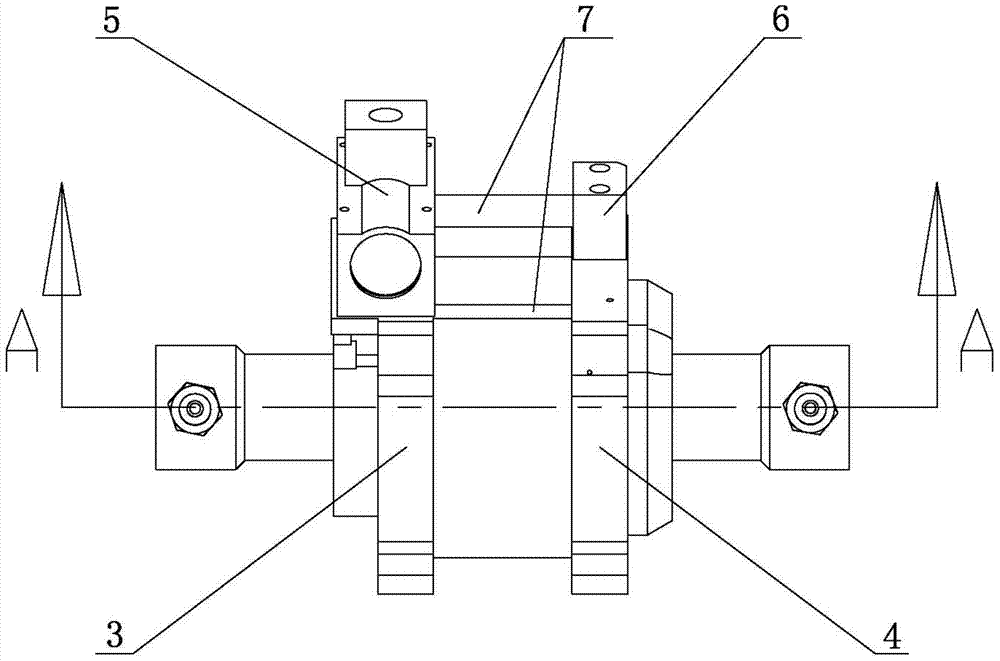
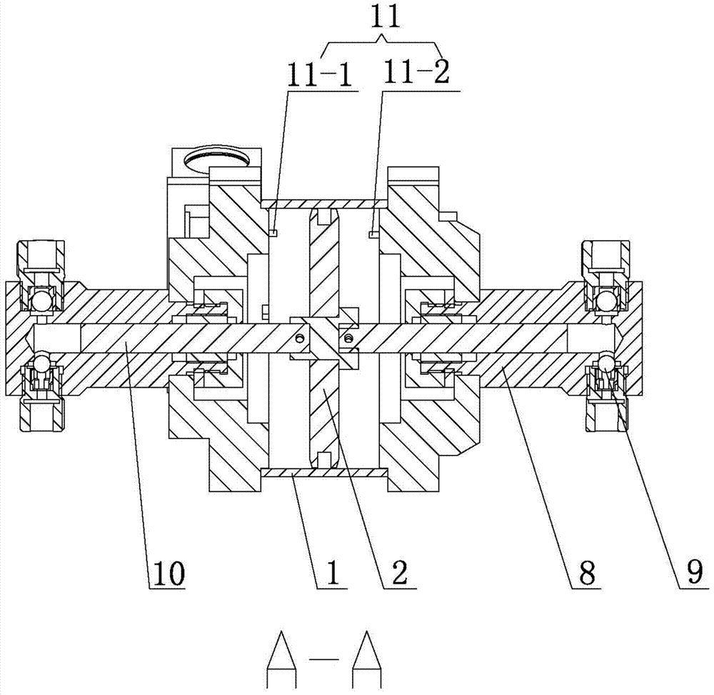
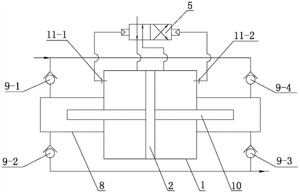
[0031] Please refer to the attached figure 1 to attach Figure 18 As shown, the present invention is an integrated valve type air-driven liquid booster pump, which consists of a low-pressure cylinder 1, a booster piston 2, a front end cover 3, a rear end cover 4, an integrated valve 5, a diverter head 6, and an air guide tube. 7. High-pressure cylinder 8, one-way valve 9, plunger 10 and pilot valve 11 are assembled.

[0032] Wherein, the front end cover 3 and the rear end cover 4 are respectively arranged at both ends of the low-pressure cylinder 1; the booster piston 2 is housed in the low-pressure cylinder 1, and the plunger 10 is respectively installed at both ends thereof. The booster piston 2 divides the low-pressure cylinder 1 into two left and right driving chambers, which are sealed with an O-ring. The plunger 10 is pin-connected with the booster piston 2, and the booster piston 2 drives the plunger 10 to move.

[0033] The integrated valve 5 is installed on the fro...


PUM


Abstract

The invention relates to a pile-up valve type gas-driving liquid booster pump which comprises a low-pressure cylinder barrel, a booster piston, a front end housing, a rear end housing, a pile-up valve, a flow guiding head, an air guiding pipe, high-pressure cylinder barrels, one-way valves, plungers and pilot valves; the front end housing and the rear end housing are arranged at the two ends of the low-pressure cylinder barrel respectively; the booster piston is contained in the low-pressure cylinder barrel and the two ends of the booster piston are respectively provided with one plunger; the pile-up valve is installed on the front end cover and connected with the flow guiding head arranged on the rear end cover through the air guiding pipe; the high-pressure cylinder barrels are arranged on the end portion of the front end cover and the end portion of the rear end cover respectively and two one-way valves are arranged on each high-pressure cylinder barrel; the pivot valves are integrated into the front end cover and the rear end cover respectively. According to the pile-up valve type gas-driving liquid booster pump, the booster piston is controlled to automatically conduct reversing by the pile-up valve and external power is not needed; the pile-up valve is large in drift diameter and flow, the boosting speed is high, and the shortage that a small-drift-diameter control valve booster pump is low in boosting speed is overcome; meanwhile, the pump is a dual-purpose pump, so that high-pressure fluid is continuously output, pressure fluctuation is small, and efficiency is high.

Description

technical field [0001] The invention relates to a booster pump, in particular to a gas-driven liquid booster pump using an integrated valve to control the automatic reversing of a booster piston, referred to as an integrated valve type gas-driven liquid booster pump, which belongs to the technical field of booster pumps. Background technique [0002] The air-driven liquid booster pump is a new type of power source developed in recent years. Domestic research on air-driven hydraulic pumps started relatively late, mainly relying on the introduction of foreign advanced products and technologies. However, after more than 60 years of development, the technical performance of foreign air-driven hydraulic pumps has matured. More representative ones are American Haskel, Interface Device, SC and German Maximator. [0003] The gas-driven liquid booster pump uses the area difference of two series-connected differential pistons to convert the low pressure on the large-area piston into ...

Claims


Application Information

Patent Timeline
IPC IPC(8): F04B9/12F04B53/10
Inventor 向忠刘剑胡旭东史伟民
Owner ZHEJIANG SCI-TECH UNIV
Learn More