Stope route arrangement mode and method beneficial to roof-contacted filling

A layout method and mining approach technology, applied to fillings, safety devices, mining equipment, etc., can solve problems such as complex construction management, high safety risks, and high technical level requirements, and achieve simple process and construction management, and reduce support The effect of simple cost and recovery process

Active Publication Date: 2014-03-05
南京银茂铅锌矿业有限公司
View PDF5 Cites 22 Cited by
  • Summary
  • Abstract
  • Description
  • Claims
  • Application Information

AI Technical Summary

Problems solved by technology

However, in this method, the second-stage approach roof support has a large amount of work and high cost. Since the anchor cable only plays a role in pulling and hoisting the second-stage approach roof ore body, it does not belong to active support, so the support effect is not ideal. Because the roof ore body is in an upside-down shape, the safety risk is relatively high during the second-stage approach; the first-stage mining approach cannot realize timely excavation and gangue filling at the footwall, and after the second-stage approach is completed, the footwall will be excavated within the proper engineering distance It is far away, so the tunneling gangue filling is unfavorable and complicated; in addition, the connection road outside the vein of the first-stage mining approach must be filled after the second-stage mining approach is completed; the construction management of this method is extremely complicated, and the technical level is relatively high; therefore, it is difficult to popularize Big

Method used


Image

  • Stope route arrangement mode and method beneficial to roof-contacted filling
  • Stope route arrangement mode and method beneficial to roof-contacted filling
  • Stope route arrangement mode and method beneficial to roof-contacted filling

Examples


Embodiment Construction

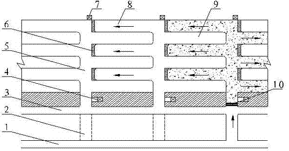
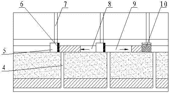
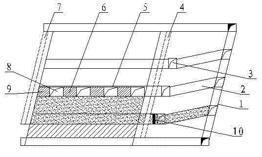
[0028] The construction scheme of the stope approach layout method that is beneficial to filling proposed by the present invention is as follows:

[0029] (1) Stope mining and cutting

[0030] Construct a downward slope connecting road 2 from the middle slope 1 to the footwall of the ore body. After reaching the design layer height of the stope, construct a connecting roadway outside the vein along the ore body at the boundary of the ore body footwall 5 to 8 meters 3. Then construct a central cutting lane 5 perpendicular to the ore body trend at intervals of 16 to 20 meters to the boundary of the ore body hanging wall along the ore body trend, and run through the Shunlu mine shaft 4 located in the ore body footwall and the ore body hanging wall The return air filling well 7. Wherein the Shunlu mine shaft 4 runs through the stope and the mining roadway at the bottom of the stope, and the air return filling shaft 7 runs through the stope and the upper return air filling roadway...


PUM


Abstract

The invention provides a stope route arrangement mode and method beneficial to roof-contacted filling. The roof-contacted filling rate can reach above 90%, filling cost is low, and the process is simple. According to the stope route arrangement mode, a mining cutting roadway is arranged perpendicular to the moving direction of an ore body, extracting drifts at two wings of the mining cutting roadway are arranged in the moving direction of the ore body in a staggered mode, a chute is arranged in a surrounding rock section of the footwall of the mining cutting roadway, the height of the extracting drifts is 3m, the length of the first extracting drift is 14-18m, the length of the second extracting drift is 16-20m, and the height of the mining cutting roadway is 4.5m. According to the stope route arrangement method, a slope ramp linking way, a footwall stope layering linking roadway and the mining cutting roadway are constructed sequentially, and the chute and a return air filling shaft are communicated; the second extracting drift is constructed after the first extracting drift is finished; brushing extraction is carried out on a temporary jamb, the width of a central mining cutting roadway is 4.5-5m, and a top plate is shaped like an arch; waste stones are dumped into the second extracting drift, the height of a smooth chute is increased by 3.5m, a filling blocking wall is erected, and filling operation is finished when the liquid level of filling material slurry is higher than the top plate of the extracting drifts by 20-30cm.

Description

technical field [0001] The invention relates to the underground mining technology of metal mines, especially the upward approach filling mining method, in particular, it is a stope approach layout method and method which is beneficial to filling and roof connection. Background technique [0002] At present, mines that use the upward filling mining method in China generally erect retaining walls at the openings of each mining approach when filling, and use grouting technology for forced filling or self-flowing filling and roofing. When the self-flowing filling is connected to the top, the filling rate is maintained at about 60%. The forced filling and roofing method has many retaining walls, complicated operation, and high filling cost. The roofing rate of self-flowing filling and roofing cannot meet the design requirements due to the low rate of filling and roofing. Therefore, it is difficult to control the damage of the surrounding rock stress to the stability of the ore bo...

Claims


Application Information

Patent Timeline
IPC IPC(8): E21F15/00
Inventor 焦鹏曹维勤张文如胡继华刘乾勇朱高杰
Owner 南京银茂铅锌矿业有限公司
Why Eureka
Try Eureka