
Soft recovery method of storage testing device embedded in high-speed flying body

A high-speed flying body and testing device technology, applied in warhead collectors, targets, offensive equipment, etc., can solve the problems of indeterminate landing points, shielding signals, and difficult to distinguish smells, and achieve the effect of convenient recovery.

Inactive Publication Date: 2014-02-26
ZHONGBEI UNIV
View PDF8 Cites 13 Cited by
  • Summary
  • Abstract
  • Description
  • Claims
  • Application Information

AI Technical Summary

Problems solved by technology

The recovery of test data needs to solve several key problems: 1. Due to the high speed of the flying object, the long flying distance and the uncertain landing point, and the flying body goes deep into the ground, it is not easy to find and excavate the flying object
3. In order to be able to locate the flying object more accurately, the predecessors thought of many ways, such as coating the flying object with a special smell, so that the police dogs can identify it, but the problem with this method lies in the ablation of gunpowder and the smell of gunpowder when launching can make the smell difficult to distinguish by itself
There is also the use of adding a long streamer to the flying body, but the problem is that the high temperature gunpowder will burn the streamer when launching
There are also people who use the GPS transmitter installed on the flying body to locate the flying body. The problem is that the flying body is generally made of ferromagnetic materials, which will shield the signal. If holes are drilled on the flying body, it will definitely affect the structure of the flying body. The cost is also relatively high

Method used


Image

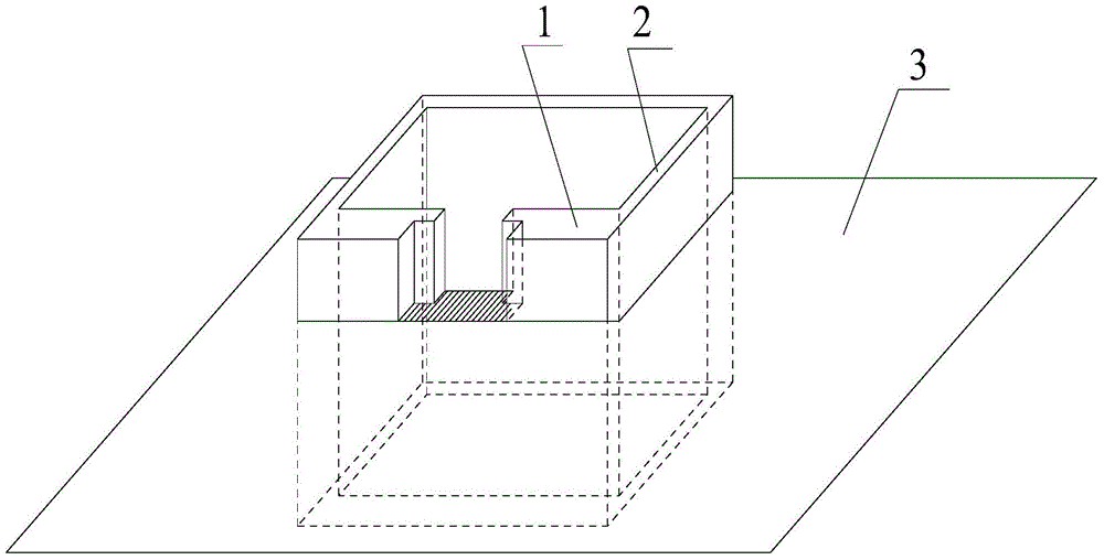
  • Soft recovery method of storage testing device embedded in high-speed flying body
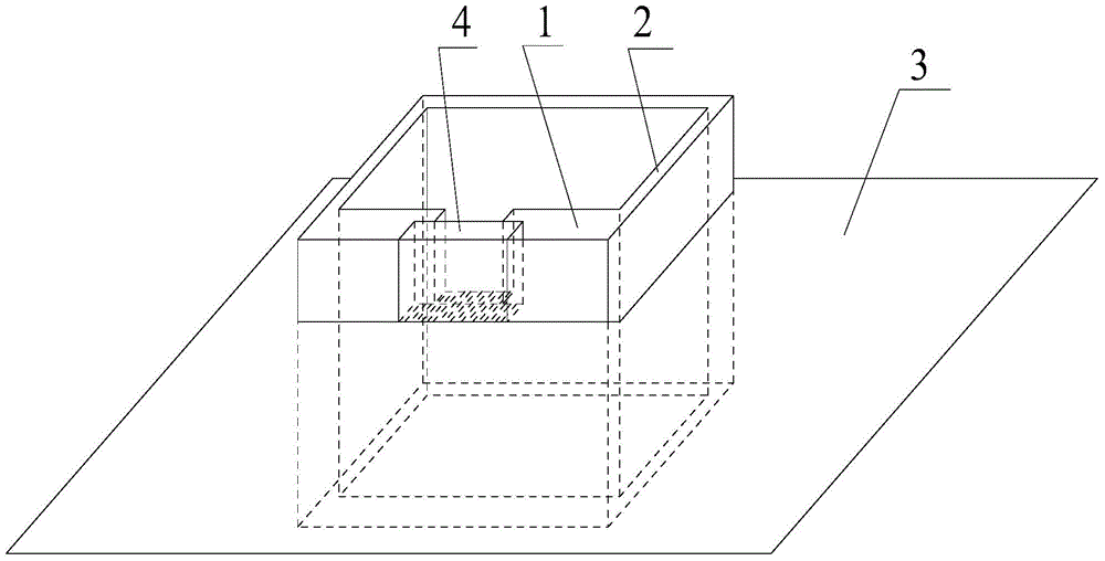
  • Soft recovery method of storage testing device embedded in high-speed flying body
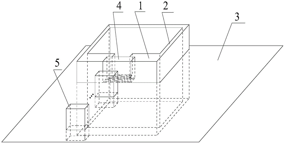
  • Soft recovery method of storage testing device embedded in high-speed flying body

Examples


Embodiment 1

[0016] Embodiment 1. The soft recovery method of the embedded storage test device in the high-speed aircraft

[0017] The method of soft recovery of the storage test device embedded in the high-speed aircraft in this example is a method of soft recovery of the storage test device embedded in the high-speed aircraft by using buffer protection equipment. The high-speed flying objects refer to various projectile flying objects that fly at a high speed of 1000m / s-1500m / s. The test devices embedded in these projectiles can be recovered safely by using soft recovery methods. The technical feature is: the speed of the high-speed flying body is 1000m / s-1500m / s, and the speed of the high-speed flying body is selected as 1500m / s in this example, and it is launched along the axis of the buffer plate. The buffer protection equipment of this example consists of several discrete buffer plates facing the high-speed flying body on the ground, a pool and a buffer plate that is tightly installe...

Embodiment 2

[0018] Embodiment 2. The soft recovery method of the embedded storage test device in the high-speed aircraft

[0019] The specific structure of the soft recovery facility adopted by the soft recovery method of the embedded storage test device in the high-speed aircraft of this example is still the same as Figure 1 to Figure 5 etc. have jointly shown that the soft recovery method of the high-speed aircraft embedded storage test device in this example is different from the soft recovery method of the high-speed aircraft embedded storage test device in Embodiment 1: 1. The speed of the high-speed aircraft is 1200m / s; 2. The buffer material used is 15 discrete red pine boards; 3. There are 6 or 7 bubble generators on the bottom of the pool. The rest of the soft recovery method of the high-speed flying body embedded storage test device that is not described is the same as that described in Embodiment 1, and will not be repeated.

Embodiment 3

[0020] Embodiment 3. The soft recovery method of the embedded storage test device in the high-speed aircraft

[0021] The specific structure of the soft recovery facility adopted by the soft recovery method of the embedded storage test device in the high-speed aircraft of this example is still the same as Figure 1 to Figure 5 etc. have jointly shown that the soft recovery method of the high-speed aircraft embedded storage test device in this example is different from the soft recovery method of the high-speed aircraft embedded storage test device in Embodiment 1 and Embodiment 2: 1. High-speed aircraft The speed is 1000m / s; 2. The buffer material used is 12 discrete red pine boards; 3. There are 5 or 6 bubble generators on the bottom of the pool. The rest of the soft recovery method of the embedded storage test device in the high-speed aircraft that is not described are the same as those described in Embodiment 1 and Embodiment 2, and will not be repeated.


PUM

PropertyMeasurementUnit
Heightaaaaaaaaaa
Widthaaaaaaaaaa
Thicknessaaaaaaaaaa

Abstract

The invention discloses a soft recovery method, using buffer protecting equipment, of a storage testing device embedded in a high-speed flying body and belongs to the technical field of buffer protection. The speed of the high-speed flying body is 1000-1500m / s. The buffer protecting equipment sequentially comprises a plurality of independent buffer plates which face the high-speed flying body and are disposed on the ground, a pool, a buffer plate mounted on the pool wall and coated with waterproof paint, water in the pool, bubbles, generated by a bubble generator, in the water, and a metal recovery net in the water. The speed of the high-speed flying body is reduced through the buffering of the buffer plates, the water and the bubbles, and the high-speed flying body at the speed lower than 20m / s is softly recovered by the metal recovery net. The method has the advantages that layer upon layer buffer protection is used, so that the storage testing device embedded in the high-speed flying body can be softly and safely recovered; by the method, the position range of a projectile flying at high speed can be determined completely, digging is not need, and convenient recovery, safety and reliability are achieved; the method is worthy of application and popularization.

Description

technical field [0001] The soft recovery method of the embedded storage test device in the high-speed flying body disclosed by the present invention belongs to the technical field of buffer protection, and specifically relates to a method of using buffer protection boards, water and water bubbles and other buffer protection facilities to protect the high-speed flying body and embedded data. A method for performing soft recycling on a storage device. Background technique [0002] In the process of testing the relevant parameters of high-speed flying objects such as projectiles by using the storage test method, the recovery of test data is very important. The recovery of test data needs to solve several key problems: 1. Due to the high speed of the flying object, the long flying distance and the uncertain landing point, and the flying body goes deep into the ground, it is not easy to find and excavate the flying object. 2. Protection of test data: Usually, in order to protec...

Claims


Application Information

Patent Timeline
IPC IPC(8): F41J13/00
Inventor 曹咏弘
Owner ZHONGBEI UNIV
Learn More