
Sampling device for timing analysis of logic analyzer

A logic analyzer and timing analysis technology, which is applied in the field of signal testing devices for the forward channel of the logic analyzer, can solve the problems of memory access speed limitation, difficult and stable realization of SRAM, etc., and achieves the effect of improving reliability.

Inactive Publication Date: 2014-02-19
JIANGSU LVYANG ELECTRONICS INSTR GROUP
View PDF6 Cites 10 Cited by
  • Summary
  • Abstract
  • Description
  • Claims
  • Application Information

AI Technical Summary

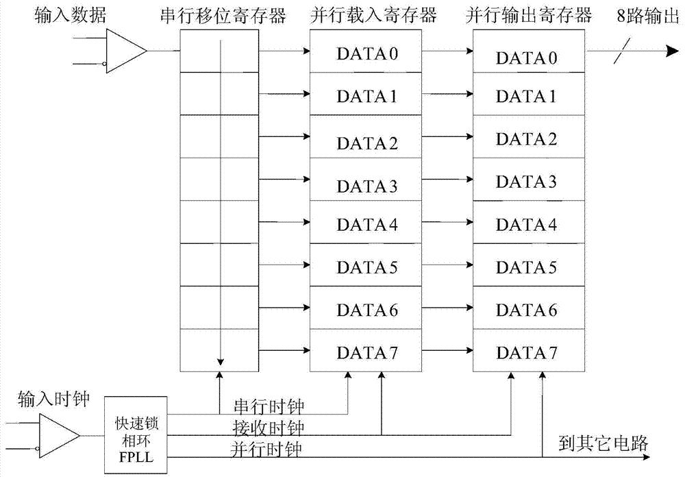
Problems solved by technology

However, as the sampling rate of the design increases, the access speed of the memory greatly limits this simple method of directly storing the input data
For example, the maximum sampling rate of

Method used


Image

  • Sampling device for timing analysis of logic analyzer
  • Sampling device for timing analysis of logic analyzer
  • Sampling device for timing analysis of logic analyzer

Examples


Embodiment Construction

[0011] The sampling device for logic analyzer timing analysis of the present invention includes a shift register, a high-speed differential interface, a parallel latch module, a high-speed clock, and a low-speed clock. The memory module and the low-speed clock are connected, and the high-speed clock and the low-speed clock are connected through a frequency divider.

[0012] The high-speed differential interface includes a serial shift register, a parallel load register, a parallel output register, and a fast phase-locked loop FPLL. The serial shift register is connected to the parallel load register, and the parallel load register is connected to the parallel output register. The phase loop FPLL is respectively connected with the serial shift register and the parallel load register through the serial clock, and the fast phase-locked loop FPLL is respectively connected with the parallel load register and the parallel output register through the receiving clock, and the fast phas...


PUM


Abstract

The invention relates to a measuring technology of a forward channel, in particular to a signal test device for a forward channel of a logic analyzer. The sampling device for timing analysis of the logic analyzer comprises a displacement register, a high-speed difference interface, a parallel latch module, a high-speed clock and a low-speed clock. The displacement register is connected with the high-speed difference interface and the high-speed clock respectively. The high-speed difference interface is connected with the parallel latch module and the low-speed clock respectively. The high-speed clock is connected with the low-speed clock through a frequency divider. According to the design, a serial-parallel conversion scheme is adopted to achieve high-speed collection of signals, after one-time serial-parallel conversion is finished, the low-speed clock is used for sampling the parallel output of the latch register, and therefore the purpose of lowering the frequency of data processing work is achieved and the reliability of work of a system is improved.

Description

technical field [0001] The invention relates to a forward channel measurement technology, in particular to a signal testing device for the forward channel of a logic analyzer. Background technique [0002] Timing analysis sampling is to collect input data on the edge of the internal clock and work asynchronously with the system clock under test. Timing analysis sampling is usually implemented by directly writing the sampling data into the memory with registers and related control circuits. However, as the sampling rate of the design increases, the access speed of the memory greatly limits this simple method of directly storing the input data. For example, the highest sampling rate of 500M for timing analysis in this design requires that the corresponding memory read and write rate should be within 2ns / Byte, but the commonly used SRAM is still difficult to realize stably. Therefore, we need to choose a more effective data acquisition scheme, which not only meets the clock r...

Claims


Application Information

Patent Timeline
IPC IPC(8): G01R31/3177
Inventor 冯锦法吕华平
Owner JIANGSU LVYANG ELECTRONICS INSTR GROUP
Learn More