
Detachable compression dustbin

A garbage bin and pin shaft technology, which is applied in the direction of garbage storage, transportation and packaging, etc., can solve the problems of automatic opening, hydraulic oil leakage, and force displacement of the piston rod of the oil cylinder, etc., and achieve high reliability and open and close action flexible effects

Active Publication Date: 2014-02-19
漳州科晖专用汽车制造有限公司
View PDF8 Cites 5 Cited by
  • Summary
  • Abstract
  • Description
  • Claims
  • Application Information

AI Technical Summary

Problems solved by technology

These locking mechanisms can basically meet the requirements for the use of garbage compactors, but when the rear door is closed, the piston rod of the locking cylinder of these locking mechanisms bears a relatively large force, and the seal between the piston rod of the oil cylinder and the cylinder body may be damaged. The leakage of hydraulic oil causes the piston rod of the oil cylinder to be displaced by force, and the back of the garbage compression box is automatically opened. Therefore, the reliability of the locking state of these locking mechanisms needs to be further improved

Method used


Image

  • Detachable compression dustbin
  • Detachable compression dustbin
  • Detachable compression dustbin

Examples


Embodiment Construction

[0020] The present invention will be further described in detail below with reference to the accompanying drawings and specific embodiments.

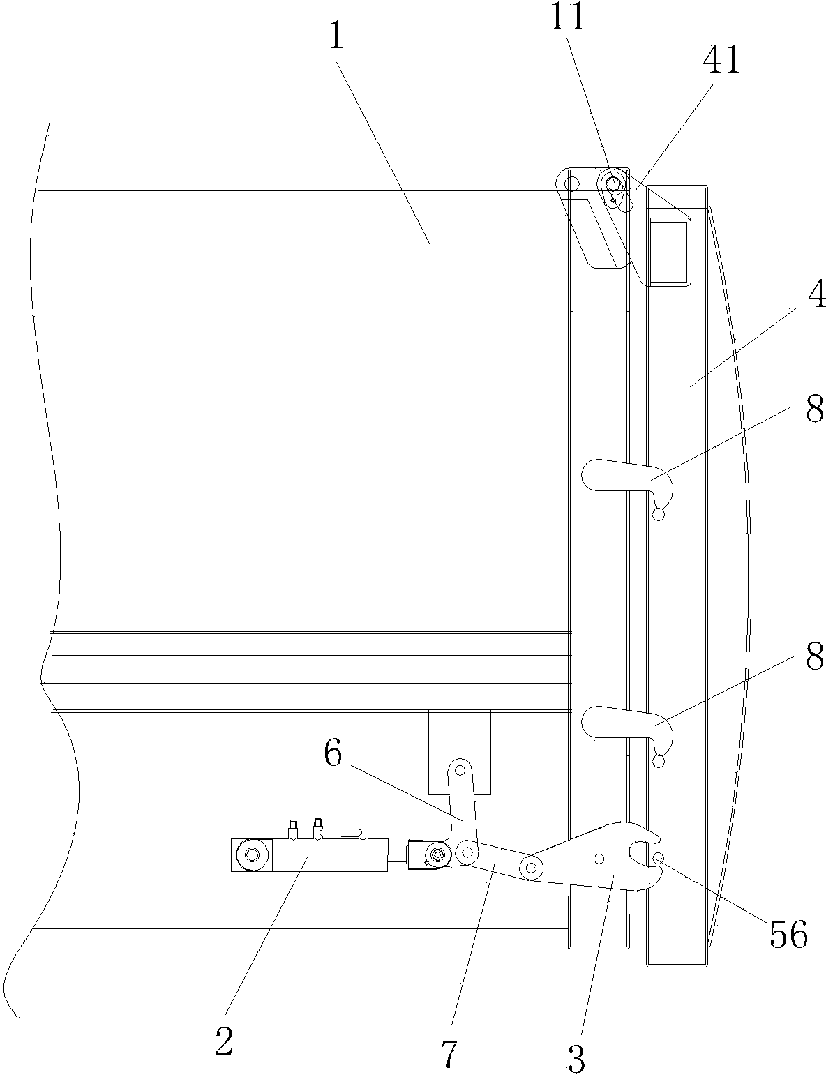
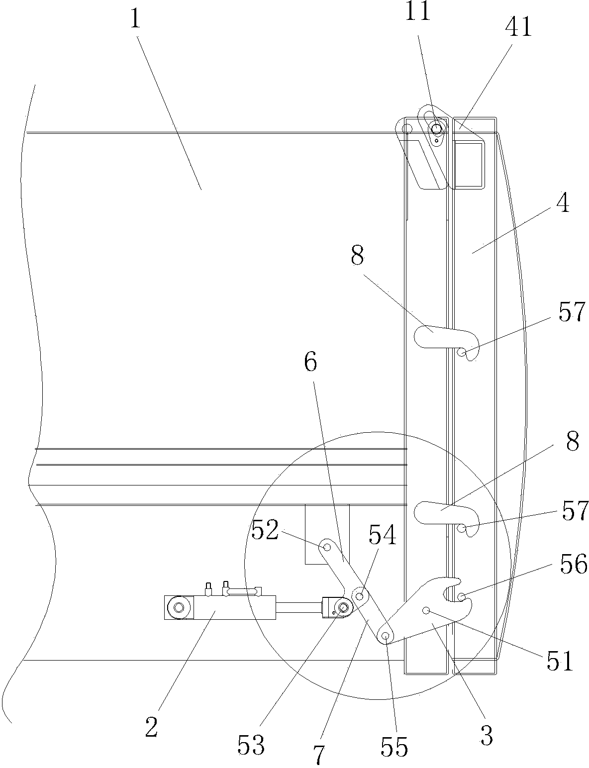
[0021] Figure 1 to Figure 5 As shown in the figure, a detachable compressed waste container includes a waste container body 1, a rear door 4, and a rear door locking mechanism. The rear door locking mechanism includes two locking oil cylinders 2, Two locking arms 3, two hanging lugs 41 are fixed on the upper ends of the two sides of the rear door 4, two hinge shafts 11 are disposed on the rear upper ends of the two sides of the dustbin body 1, and the two hanging lugs 41 are provided with long strips. The hinged through holes 411, the two hanging ears 41 are respectively sleeved on the two hinge shafts 11 by the elongated hinged through holes 411;

[0022] A first pin shaft 51 and a second pin shaft 52 are fixed at intervals on the rear lower parts of the two sides of the garbage box body 1, and the middle parts of the two locking arm...


PUM


Abstract

The invention discloses a detachable compression dustbin. The detachable compression dustbin comprises a rear door locking mechanism. The rear door locking mechanism comprises locking oil cylinders, locking arms, L-shaped connecting rods and ejector rods, wherein the middle portions of the locking arms are hinged to the lower rear portions of the side faces of the dustbin body through first hinge pins; the upper ends of the L-shaped connecting rods are hinged to the two sides of the dustbin body through second hinge pins, and the lower ends of the L-shaped connecting rods are hinged to the locking oil cylinders through third hinge pins; one ends of the ejector rods are hinged to the middle portions of the L-shaped connecting rods through fourth hinge pins, and the other ends of the ejector rods are hinged to the front ends of the locking arms through fifth hinge pins; grooves are formed in the rear ends of the locking arms and matched with sixth hinge pins fixed to the side faces of a rear door; locking hooks are fixed to the rear ends of the side faces of the dustbin body, and seventh hinge pins are fixed to the middle portions of the two sides of the rear door and matched with the locking hooks. When the rear door is locked, the centers of the second hinge pins, the centers of the fourth hinge pins and the centers of the fifth hinge pins are located in the same straight lines which are perpendicular to the straight lines formed by connecting the centers of the fifth hinge pins and the centers of the first hinge pins. According to the detachable compression dustbin, the rear door is flexible to open and close and reliable in locking.

Description

technical field [0001] The invention relates to the technical field of manufacture of a compression type garbage box, in particular to a detachable type of compression type garbage box. Background technique [0002] When compressing the garbage can, the garbage is squeezed into the garbage can through the garbage compression mechanism, so as to improve the carrying capacity of the garbage can. Therefore, both the body and the front and rear doors of the compression type waste container need to have sufficient strength, and the weight and force of the rear door of the waste container are relatively large. [0003] Due to the relatively large weight and force of the rear door of the compression type waste bin, the requirements for the locking mechanism of the rear door are also relatively high. At present, various manufacturers have designed a variety of locking mechanisms. For example, on June 27, 2012, an invention patent with the patent number ZL201120402551.2 titled "A re...

Claims


Application Information

Patent Timeline
IPC IPC(8): B65F3/24
Inventor 杨志强
Owner 漳州科晖专用汽车制造有限公司
Learn More