Optional voltage drain circuit structure

A circuit structure and drainage technology, applied in the field of optional voltage drainage circuit structure, can solve the problems of inability to distinguish pipeline induced interference, difficult monitoring and maintenance, pipeline hydrogen evolution reaction, etc., and achieve safe, reliable and economical pipeline drainage operation. Operating cost, effect of avoiding hydrogen evolution reaction

Active Publication Date: 2016-08-17
CHINA RAILWAY DESIGN GRP CO LTD +1
View PDF1 Cites 0 Cited by
  • Summary
  • Abstract
  • Description
  • Claims
  • Application Information

AI Technical Summary

Problems solved by technology

This method is simple in structure, but its intelligence is poor, and it is difficult to monitor and maintain. The main disadvantages are as follows:
[0003] 1. Since the protection voltage of the pipeline is not set, and it is impossible to distinguish whether there is induction interference on the pipeline, direct drainage is adopted, so the buried magnesium anode will also cause consumption when the drainage is not actually required, thereby reducing the service life of the anode and increasing operating costs;
[0004] 2. Due to the influence of parameters such as the working voltage of the diode, when the negative potential of the magnesium anode is insufficient after peroxidation, or when the ground potential of the tube is lower than the normal working voltage of the diode, the diode cannot conduct forward smoothly, and there is a blind area for drainage;
[0005] 3. When the diode is damaged by reverse breakdown, the negative potential of the magnesium anode will be completely applied to the pipeline. At this time, the pipeline will be overprotected, and the hydrogen evolution reaction will occur in the pipeline, causing the insulation layer of the pipeline to fall off, which will accelerate the pipeline. oxidation corrosion
However, the current drainage structure is based on the principle of forced drainage, which cannot meet the new requirements.

Method used


Image

  • Optional voltage drain circuit structure
  • Optional voltage drain circuit structure

Examples


Embodiment Construction

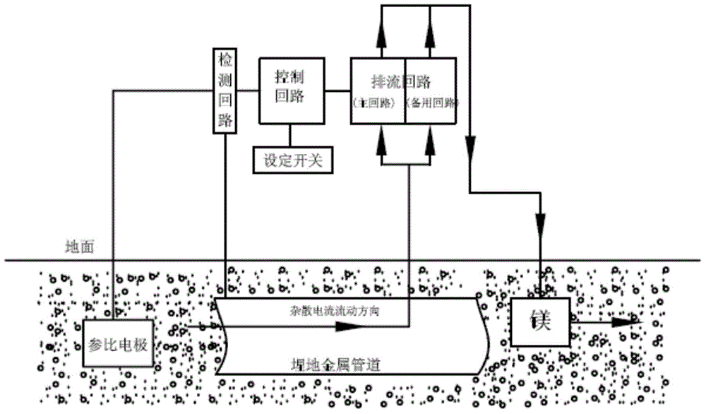
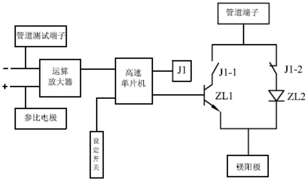
[0019] The structure of the optional voltage drain circuit of the present invention is described in conjunction with the accompanying drawings.

[0020] The design idea of ​​the optional voltage type drainage circuit structure of the present invention is based on the fact that the cathodic protection potential is set according to the use conditions, and the drainage can be performed only when the setting conditions are met, and the cathodic protection voltage is set according to the environmental conditions, so as to realize Intelligent circuit structure that needs drainage. Connect one end of the drainage circuit to the metal pipe, and the other end to the magnesium anode, compare the measured voltage of the pipe with the preset voltage of the setting switch through the detection circuit, and according to the logical judgment result, the control circuit determines whether the drainage circuit is conducting Still due. At the same time, the drainage circuit is equipped with a ...


PUM


Abstract

The invention provides an optional voltage drainage circuit structure, the circuit structure includes a drainage circuit, a control circuit, a detection circuit and a setting switch; the detection circuit is connected to the pipeline test terminal and the reference electrode of the metal pipeline protection circuit structure, and sequentially It is connected with the control circuit and the drainage circuit, and the control circuit is connected with the setting switch; the drainage circuit is divided into a main circuit and a backup circuit, and is connected with the magnesium anode of the metal pipeline protection circuit structure. Effects of the present invention Through the circuit, the intelligent "on-demand drainage" function is realized, and there is no drainage blind zone voltage in the entire drainage system, which greatly reduces the consumption of magnesium anodes and saves operating costs. Every 2 to 4 hours, the control circuit will regularly check the working status of the main circuit. If the main circuit is damaged abnormally, it will immediately switch to the backup circuit, so that the negative potential of the magnesium anode is isolated by the backup circuit and cannot be completely applied to the pipeline, avoiding Hydrogen evolution reaction occurs in metal pipelines, insulation layer of pipelines falls off, etc., which makes pipeline drainage operation safer and more reliable.

Description

technical field [0001] The invention relates to an optional voltage type drainage circuit structure for protecting oil and gas metal pipelines along electrified railways from being corroded by stray currents. Background technique [0002] At present, the protection of oil and gas metal pipelines along the electrified railway mostly adopts the forced drainage method, that is, no matter what the potential of the pipeline is, whether drainage is required, the drainage device directly connects the pipeline and the magnesium anode through a diode to perform forced drainage. This method is simple in structure, but its intelligence is poor, and it is difficult to monitor and maintain. The main disadvantages are as follows: [0003] 1. Since the protection voltage of the pipeline is not set, and it is impossible to distinguish whether there is induction interference on the pipeline, direct drainage is adopted, so the buried magnesium anode will also cause consumption when the draina...

Claims


Application Information

Patent Timeline
Patent Type & Authority Patents(China)
IPC IPC(8): C23F13/06
Inventor 孙震洋王双平陈敬和申满愉陈杰张喜海邢晓乾
Owner CHINA RAILWAY DESIGN GRP CO LTD
Why Eureka
Try Eureka