
Rolling fracture device for brittle material substrates

A brittle material substrate and fracture technology, which is used in fine working devices, glass cutting devices, stone processing tools, etc., can solve the problems of debris generated on the cutting surface, pollution of the substrate surface, and difficult separation, etc., to improve the breaking force. , the effect of preventing pollution

Active Publication Date: 2016-11-02
MITSUBOSHI DIAMOND IND CO LTD
View PDF9 Cites 0 Cited by
  • Summary
  • Abstract
  • Description
  • Claims
  • Application Information

AI Technical Summary

Problems solved by technology

According to this, there is a problem that it is difficult to separate the left and right sides of the brittle material substrate after breaking, making the separation difficult.
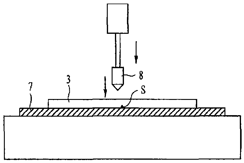
[0005] In addition, since the surface on which the scored line S is formed is in contact with the surface of the cushion sheet 7, friction is caused while it is pressed toward the cushion sheet 7, and it is broken, so there is also a problem of chipping on the broken surface.
In addition, in the prior known breaking device as mentioned above, in order to break the brittle material substrate, it is necessary to reverse the substrate by using an adsorption reversing device, so there is also the possibility that contamination of the substrate surface is likely to occur due to adsorption. problem points
Furthermore, once the position facing the back of the scribed line S is not pressurized by the breaking rod 8, it cannot be broken along the scribed line S correctly. Once the position of the brittle material substrate 3 is slightly shifted by When the breaking rod 8 is pressurized, it cannot be broken correctly along the scoring line S, and the problem of breaking in the state of either left or right deviation occurs in the past.
[0006] It can be seen that the above-mentioned existing breaking device obviously still has inconvenience and defects in structure and use, and needs to be further improved urgently.
In order to solve the above-mentioned problems, the relevant manufacturers have tried their best to find a solution, but for a long time no suitable design has been developed, and the general product has no suitable structure to solve the above-mentioned problems. This is obviously the relevant industry. Urgent problem

Method used


Image

  • Rolling fracture device for brittle material substrates
  • Rolling fracture device for brittle material substrates
  • Rolling fracture device for brittle material substrates

Examples


Embodiment Construction

[0027] In order to further explain the technical means and effects of the present invention to achieve the intended purpose of the invention, the specific implementation of a rolling fracture device for brittle material substrates proposed according to the present invention, Structure, characteristic and effect thereof are as follows in detail.

[0028] Hereinafter, preferred embodiments of the present invention will be described in more detail with reference to the drawings. In addition, in the embodiments of the present invention, descriptions of constituent elements that are the same as or similar to those in the conventional art are omitted by using the same reference numerals.

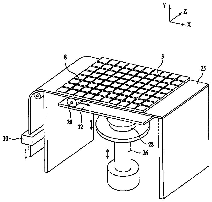
[0029] The rolling fracture device of the brittle material substrate of the embodiment of the present invention, such as image 3 As shown, a lifting part 26 that can be raised and lowered by a cylinder or the like is provided, and a rotating part 28 is attached to the upper part of the lifting p...


PUM


Abstract

The invention provides a rolling break apparatus for a brittle material substrate capable of breaking the brittle material substrate provided with scale lines. The rolling break device comprises a flexible carrying cushion (25), on which is disposed a brittle material substrate (3) provided with scale lines (S); a tensioning part (30), which is disposed on one side end of the flexible carrying cushion (25), and is used to provide the tensioning force in a non-flexible way; a pressing moving rolling part (20), which is disposed on the side of the flexible carrying cushion (25)opposite to the side provided with the brittle material substrate (3); and an elevating part (26) capable of moving the pressing moving rolling part (20) upwards and downwards by pressing the lower part of the flexible carrying cushion (25) of the pressing moving rolling part (20).

Description

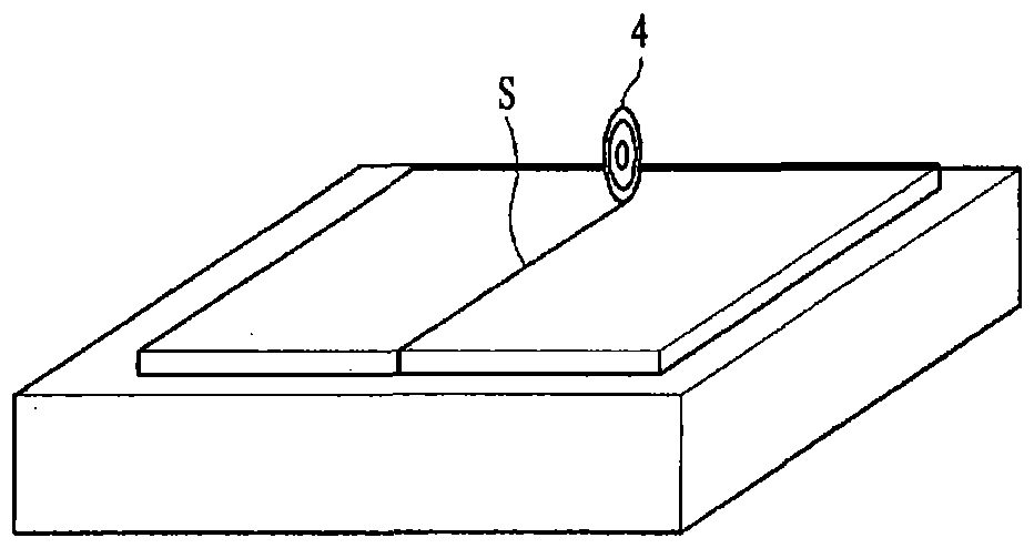
technical field [0001] The present invention relates to a rolling fracture device, and more particularly to a rolling fracture device for a brittle material substrate capable of easily breaking a brittle material substrate on which a scribe line is formed. Background technique [0002] In general, a brittle material substrate is manufactured in a large size, and the user cuts the substrate into a desired size for use. For the existing known breaking device of breaking such a large brittle material substrate, refer to figure 1 and figure 2 Be explained. [0003] refer to figure 1 , in order to break the large brittle material substrate 3 , first, the scribe line S is formed on the surface of the large brittle material substrate 3 using the cutter wheel 4 . Thereafter, the brittle material substrate 3 is reversed 180 degrees by an adsorption inversion device (not shown) so that the upper and lower planes are aligned. Such as figure 2 As shown, if the surface of the bri...

Claims


Application Information

Patent Timeline
Patent Type & Authority Patents(China)
IPC IPC(8): B28D1/32
CPCB28D5/04C03B33/033C03B33/037Y02P40/57
Inventor 金必钟
Owner MITSUBOSHI DIAMOND IND CO LTD
Learn More