
Vibration actuator

A vibration actuator and axis technology, which is applied to fluids, electrical components, and electromechanical devices that use vibration, can solve problems such as abnormalities and unstable vibrations, and achieve the effect of preventing abnormal sounds and stabilizing vibrations

Active Publication Date: 2014-02-12
COPAL CO LTD
View PDF8 Cites 31 Cited by
  • Summary
  • Abstract
  • Description
  • Claims
  • Application Information

AI Technical Summary

Problems solved by technology

As a result, the first compression coil spring, which expands and contracts repeatedly when the hammer vibrates, rubs or collides with the outer peripheral surface of the protrusion, and the first compression coil spring may generate abnormal noise at the contact portion.
In addition, when the first compression coil spring rubs against or collides with the protrusion, there is a problem that the amplitude of the hammer is affected and the amount of vibration becomes unstable.
In particular, the wire diameter of the compression coil spring of a small-sized vibration actuator is very small, and the compression coil spring itself is also easily twisted, so the above-mentioned problems are likely to occur.
[0007] In addition, in this patent document 1, there is no technical idea of ​​effectively utilizing the convex part of the hammer as a part of the hammer, and the spring seat is only made by making the end of the hammer concave.

Method used


Image

  • Vibration actuator
  • Vibration actuator
  • Vibration actuator

Examples


Embodiment Construction

[0044] Hereinafter, preferred embodiments of the vibration actuator of the present invention will be described in detail with reference to the drawings.

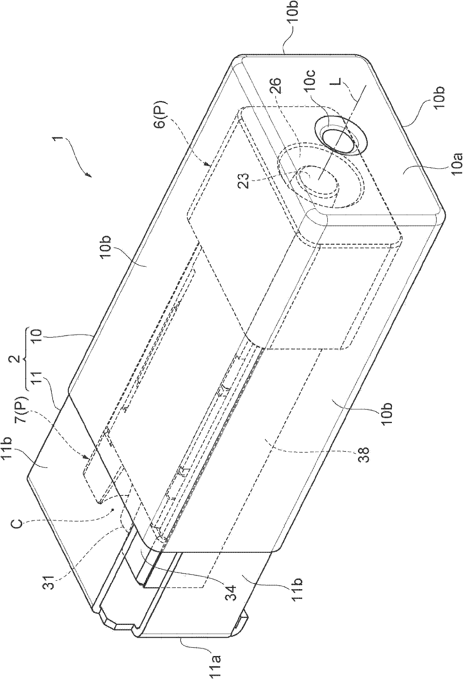
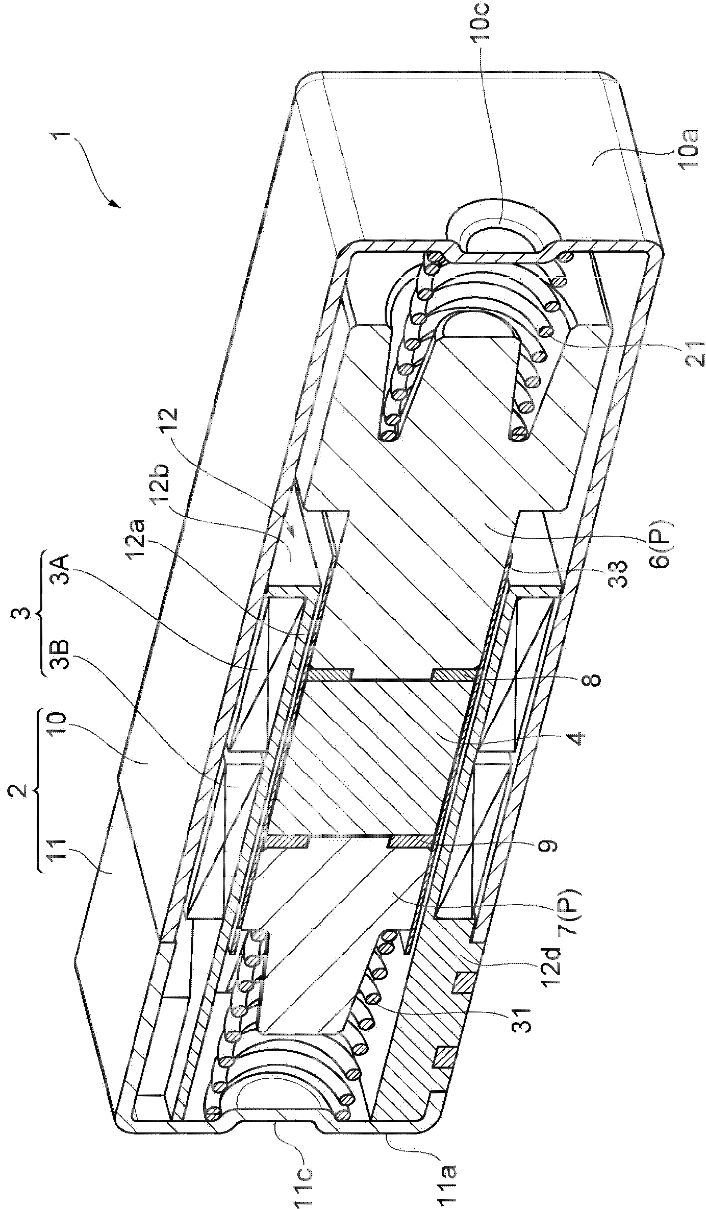
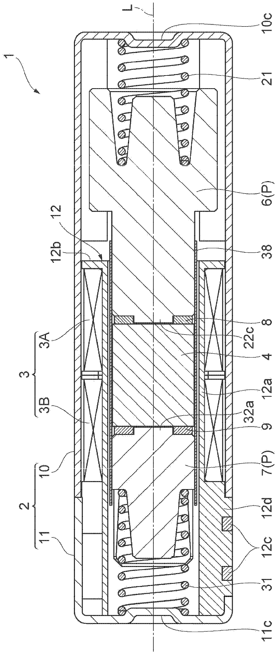
[0045] Such as Figure 1 ~ Figure 3 As shown, a small vibration actuator 1 has a housing 2 composed of a hollow rectangular parallelepiped with a height of 4 mm x a width of 6 mm x a length of 15 mm. A coil 3 , a rectangular parallelepiped magnet 4 , a first weight 6 and a second weight 7 , and an annular first pole piece 8 and second pole piece are accommodated in a case 2 made of a magnetic body. 9, wherein the above-mentioned coil 3 is wound around the vibration axis L of the casing 2 to form a rectangular cross-section, the above-mentioned magnet 4 is surrounded by the coil 3, and the above-mentioned first hammer part 6 and the second hammer part 6 are arranged as Adjacent to both sides of the magnet 4 in the direction of the vibration axis L of the casing 2 , the first pole piece 8 and the second pole piece 9 are fixed...


PUM


Abstract

A first weight portion of a vibration actuator includes an inner-side enlarged portion that protrudes from an end portion of a solid head in a direction of a vibration axis and that is inserted into an opening portion extending within a first compression coil spring along the direction of the vibration axis. An outer peripheral surface of the inner-side enlarged portion becomes continuously smaller in diameter from a base end towards a free end, with the vibration axis being the center of the diameter. That is, the inner-side enlarged portion has the shape of a truncated cone. The inner-side enlarged portion is inserted into the opening portion of the first compression coil spring and the opening portion is utilized to change the length of the inner-side enlarged portion in the direction of the vibration axis, thereby changing the mass of the first weight portion.

Description

technical field [0001] The present invention relates to a vibration generating source for notifying a user of an incoming call from a mobile wireless device such as a mobile phone, a vibration generating source for transmitting the operating tactile sensation of a touch panel of a mobile wireless device, and the presence of a game machine to fingers and hands, etc. Small vibration actuators used in Background technique [0002] Currently, there is Japanese Patent Application Laid-Open No. 2003-220363 as a technology in the above field. The vibration actuator described in this publication includes a cup-shaped yoke within a housing (frame). A cylindrical magnet is fixed on one side and a hammer is fixed on the other side across the bottom of the yoke, and a coil is arranged between the magnet and the yoke. In addition, a first compression coil spring is disposed between the hammer and one end of the case in the direction of the vibration axis, and a second compression coil ...

Claims


Application Information

Patent Timeline
Patent Type & Authority Applications(China)
IPC IPC(8): B06B1/04
CPCH02K33/18H02K33/16
Inventor 远藤雅也殿贝佳英
Owner COPAL CO LTD
Learn More