
Automatic fire-extinguishing device

An automatic fire extinguishing and igniter technology, applied in fire rescue and other directions, can solve problems such as false opening, difficulty in fighting fires, fire loss, etc., and achieve the effect of preventing secondary recombustion

Active Publication Date: 2014-02-12
山东卓辰科技服务有限公司
View PDF3 Cites 11 Cited by
  • Summary
  • Abstract
  • Description
  • Claims
  • Application Information

AI Technical Summary

Problems solved by technology

In this way, in order to prevent the fire from spreading when starting, the relevant temperature or smoke parameter values ​​are often set to be relatively small, and the phenomenon of false opening often occurs, which brings unnecessary troubles to users; or, in order to avoid accidental For the opening phenomenon, a relatively high parameter value is selected, but because the fire is already large or spreading, it often happens that people are too late to evacuate or cannot be evacuated effectively, especially when a fire occurs in a vehicle, because the fire-prone parts of the car are generally concentrated in the In the engine compartment, and the engine compartment of a large passenger car is at the rear of the vehicle body. Once the fire is caught, the driver is not easy to notice. When the fire is large enough to attract attention, the door is often unable to be opened because the control circuit is blown, causing heavy personal and property losses.
Moreover, the general automatic fire extinguisher has no alarm function after spraying the fire extinguishing agent, so as to remind the relevant personnel to take necessary measures to prevent the occurrence of secondary resurgence.
In addition, such as some buildings, warehouses, etc., although there are fire-fighting facilities, there are still fires when the fire is discovered, and it is difficult to put out the fire. often has caused losses

Method used


Image

  • Automatic fire-extinguishing device

Examples


Embodiment Construction

[0017] Specific embodiments of the present invention will be described in detail below in conjunction with the accompanying drawings.

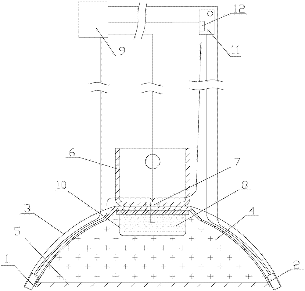
[0018] like figure 1 As shown, the automatic fire extinguishing device mainly includes: a casing 3 provided with an injection port, a fire extinguishing agent 4 is placed in the casing 3, and a film 5 whose pressure resistance meets the set requirements is sealed at the injection port, 3 is also fixedly provided with a detonator; the detonator is mainly composed of a film 10 whose pressure resistance meets the set requirements, a gas generating agent 8 wrapped in the film 10, and an igniter 7. One contact of sensor controllers 1 and 2 with a fixed value, the other contact of sensor controller 1 with a higher set value is respectively connected to the igniter 7 and alarm 11, and the sensor with a smaller set value Another contact of controller 2 is connected to alarm 11. A backup ignition circuit with a manual switch 12 is provided between th...


PUM


Abstract

The invention discloses an automatic fire-extinguishing device, which can automatically detect surrounding environment parameters, can give early warning in advance to remind a user of confirming while a fire behavior possibly appears, and can timely spray a fire extinguishing agent and alarm again automatically when the fire behavior happens and environment parameters reach set values. The automatic fire-extinguishing device comprises a shell with a spraying port, wherein the fire extinguishing agent is placed in the shell; a film with pressure resistance satisfying set requirements is sealed and covered on the spraying port; an exploder is further fixedly arranged in the shell; the exploder mainly consists of the film satisfying the set requirements, a gas generating agent covered in the film and an igniter, and further comprises an alarm, wherein two sensing controllers which are connected with a power supply and have different set values are arranged outside the shell; one sensing controller with a greater set value is connected with the igniter by a cable; the igniter is connected with the alarm by a remote cable; the other sensing controller with a smaller set value is directly connected with the alarm by the remote cable.

Description

technical field [0001] The invention relates to an automatic fire extinguishing device. Background technique [0002] Existing automatic fire extinguishers do not have an early warning function, and can only be automatically activated when a fire occurs. In this way, in order to prevent the fire from spreading when starting, the relevant temperature or smoke parameter values ​​are often set to be relatively small, and the phenomenon of false opening often occurs, which brings unnecessary troubles to users; or, in order to avoid accidental For the opening phenomenon, a relatively high parameter value is selected, but because the fire is already large or spreading, it often happens that people are too late to evacuate or cannot be evacuated effectively, especially when a fire occurs in a vehicle, because the fire-prone parts of the car are generally concentrated in the In the engine compartment, while the engine compartment of a large passenger car is at the rear of the vehic...

Claims


Application Information

Patent Timeline
Patent Type & Authority Applications(China)
IPC IPC(8): A62C35/08A62C37/08
Inventor 黄泽铭茅忠平刘建平
Owner 山东卓辰科技服务有限公司
Learn More