Battery for vehicle and method for manufacturing battery

A technology for batteries and vehicles, which is applied in the fields of batteries for vehicles and manufacturing of batteries, can solve problems such as high consumption, and achieve the effects of low consumption and light weight

Active Publication Date: 2016-06-01
AUDI AG
View PDF10 Cites 0 Cited by
  • Summary
  • Abstract
  • Description
  • Claims
  • Application Information

AI Technical Summary

Problems solved by technology

[0010] In the batteries disclosed in these prior art, it is relatively expensive to bring the cooling device into good heat-conducting contact with the battery cells.

Method used


Image

  • Battery for vehicle and method for manufacturing battery
  • Battery for vehicle and method for manufacturing battery
  • Battery for vehicle and method for manufacturing battery

Examples


Embodiment Construction

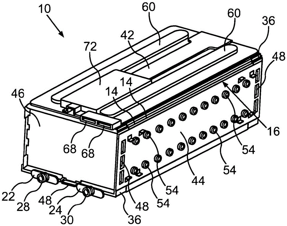
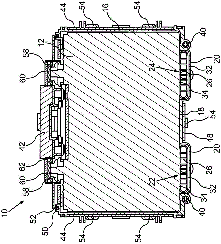
[0035] figure 1 The illustrated battery 10 for a vehicle is designed, for example, as a lithium-ion battery. The battery 10 has a plurality of battery cells 12 which are electrically insulated from one another by separators 14 made of plastic, also called separators (see Figure 6 ). The aforementioned prismatic battery cells 12 form a stack.

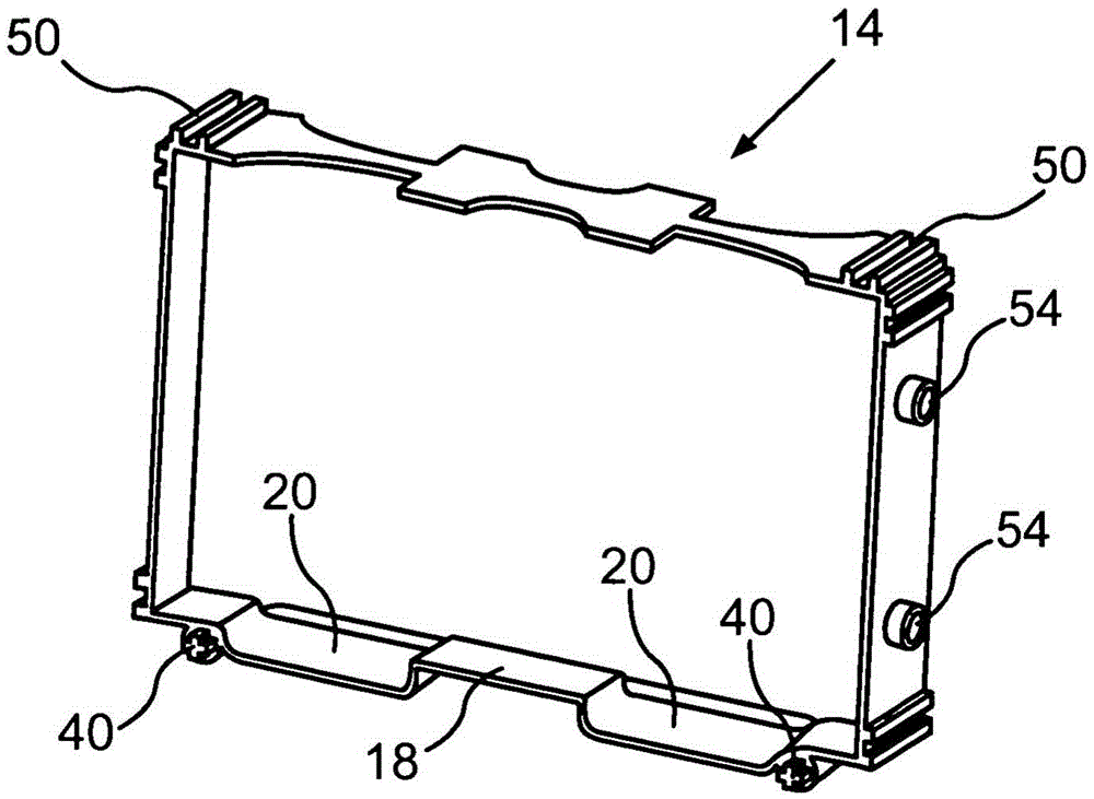
[0036] The separators 14 connected to each other by an adhesive constitute the side walls 16 and the bottom plate 18 of the casing of the battery 10 (see figure 2 ), in which a stack of battery cells 12 is accommodated. In the area of ​​the housing floor 18 formed by the partition 14, two channels 20 are formed by the partition 14 (see figure 2 ), which accommodates the two profile parts 22, 24 of the cooling device (see figure 1 ).

[0037] The profile parts 22, 24 are designed as flat tubes through which the coolant can flow, and in the flat tubes, cooling fins 26 form a plurality of cooling passages parallel to each other (se...


PUM


Abstract

The invention relates to a battery (10) for a vehicle. The battery has: a plurality of battery cells (12) arranged in a housing (16, 18, 20) of the battery (10); and cooling means (22, 24) for removing heat from the battery cells (12) ). A material (32) is inserted between the housing (20) and the cooling device (22, 24), the material occupying a first volume in a base state and an increased volume in an expanded state compared to the first volume. The cooling device ( 22 , 24 ) is pressed against the battery cell ( 12 ) by the material ( 32 ) converted into its expanded state. Furthermore, the invention relates to a method for producing such a battery ( 10 ).

Description

technical field [0001] The invention relates to a battery for a vehicle, in which a plurality of battery cells are arranged in a battery housing. The battery has a cooling device for removing heat from the battery cells. The interspace provided between the housing and the cooling device is filled with a material which occupies a first volume in the base state and an increased volume in the expanded state compared to the first volume. The cooling device squeezes the battery cells by the material transitioning into its expanded state. The invention also relates to a method for producing such a battery. Background technique [0002] DE 10 2007 010 745 A1 describes a battery for a vehicle having a plurality of battery cells arranged in a battery housing. A heat-conducting plate with cooling channels is provided on the top of the battery cell for the heat-conducting medium. A heat-conducting foam, for example polyurethane foam, is arranged between the battery cell connector a...

Claims


Application Information

Patent Timeline
Patent Type & Authority Patents(China)
IPC IPC(8): H01M10/613H01M10/6554H01M10/6556H01M10/625
CPCH01M10/613H01M10/647H01M10/6554H01M10/6556H01M10/6567H01M10/625Y02E60/10Y10T29/49108Y02P70/50H01M10/049
Inventor H·费斯A·特拉克R·迈施
Owner AUDI AG
Why Eureka
Try Eureka