Lifting device for electrolytic copper plates
An electrolytic copper plate and hoisting device technology, used in transportation and packaging, load hoisting elements, etc.
- Summary
- Abstract
- Description
- Claims
- Application Information
AI Technical Summary
Problems solved by technology
Method used
Image
Examples
Embodiment 1
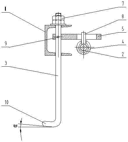
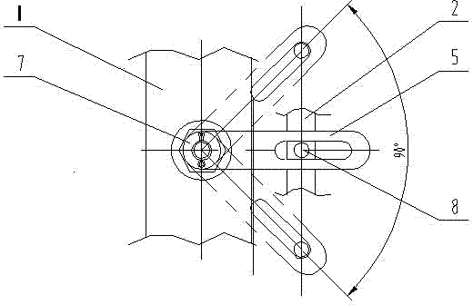
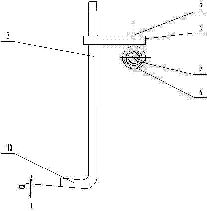
[0021] Example 1 Such as Figure 1-7 Shown: A hoisting device for electrolytic copper plates, including brackets 12 for storing electrolytic copper plates 13 arranged at equidistant intervals of 100 mm, and each side of the channel steel on both sides of the triangular frame 1 is drilled at equidistant intervals of 100 mm for installing hooks 16 through holes of 3, the spacing of through holes 100mm is equal to the spacing of the electrolytic copper plates 13 arranged and stored on the support 12, and the top of the hook 3 is fastened on the channel steel on both sides of the triangular frame 1 by nuts 7. The pendulum 5 is fastened or welded on the upper part of the hook 3 through the positioning pin 9. The pendulum 5 is provided with a long slot 11. The angle between the pendulum 5 and the horizontal plane 10 at the lower end of the hook 3 is 135°; the triangular frame 1 There are guide sleeves 4 at both ends, and the push rod 2 parallel to the channel steel on both sides o...
Embodiment 2
[0022] Example 2 Such as Figure 1-7 Shown: adopt the method for hoisting electrolytic copper plate of a kind of hoisting device described in embodiment 1, comprise:
[0023] [1] When installing the hook 3 into the through holes on the channel steel on both sides of the triangular frame 1, which are arranged equidistantly at intervals of 100 mm, first put the matching hole on the swing rod 5 into the hook 3, and pass 9 positioning pins Both sides fork 5 are fastened on the top of suspension hook 3, make the angle between fork 5 and the elbow 10 at the lower end of suspension hook 3 in the horizontal plane be 135 ° (as Figure 5 shown);
[0024] [2], put the long slot 11 of the pendulum 5 into the lever 8 of the push rod 2, so that when the push rod 2 is fully pushed in, the elbows 10 at the lower ends of the hooks 3 on both sides are perpendicular to the push rod 2 and towards the outside of the triangular frame 1 (such as Figure 7 shown);
[0025] [3] When hoisting the...
PUM
 Abstract
Description
Claims
Application Information
 - R&D
- Intellectual Property
- Life Sciences
- Materials
- Tech Scout
- Unparalleled Data Quality
- Higher Quality Content
- 60% Fewer Hallucinations
Browse by: Latest US Patents, China's latest patents, Technical Efficacy Thesaurus, Application Domain, Technology Topic, Popular Technical Reports.
© 2025 PatSnap. All rights reserved.Legal|Privacy policy|Modern Slavery Act Transparency Statement|Sitemap|About US| Contact US: help@patsnap.com


