
Rotating member limiting device used for medical equipment and medical equipment comprising same

A technology of rotating parts and medical equipment, applied in the field of medical equipment, can solve problems such as increasing the difficulty of limit, achieve reliable limit, significant practical effect, and avoid the effect of excessive rotation in one direction

Active Publication Date: 2014-01-29
BEIJING NOVEL MEDICAL EQUIP LTD
View PDF6 Cites 5 Cited by
  • Summary
  • Abstract
  • Description
  • Claims
  • Application Information

AI Technical Summary

Problems solved by technology

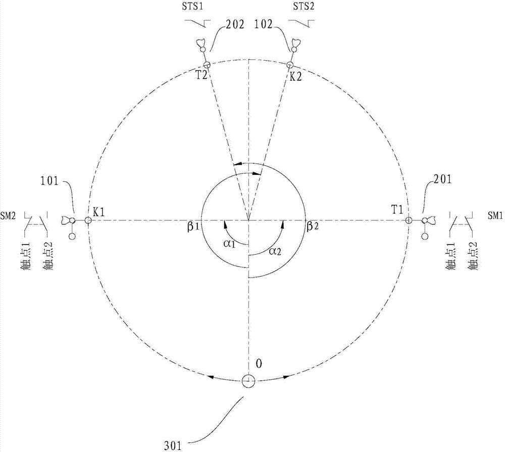
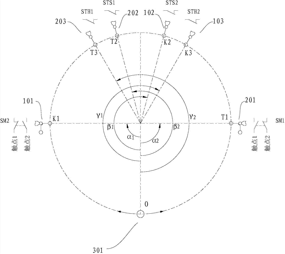
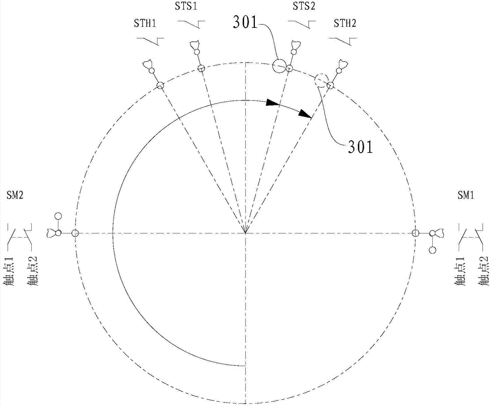
[0002] The detector of traditional human body SPECT equipment is fixed on the rotating part. The detector moves in a circle. The cable is broken, and the maximum rotation stroke of the rotating part needs to be effectively limited. However, since the detector rotates more than 180° in one direction, the motion track of the detector is repeated when it rotates clockwise or counterclockwise, which greatly improves the Limit difficulty, currently there is no good technical solution to solve this technical problem

Method used


Image

  • Rotating member limiting device used for medical equipment and medical equipment comprising same
  • Rotating member limiting device used for medical equipment and medical equipment comprising same
  • Rotating member limiting device used for medical equipment and medical equipment comprising same

Examples


Embodiment Construction

[0030] Embodiments of the present invention are described in detail below, examples of which are shown in the drawings, wherein the same or similar reference numerals designate the same or similar elements or elements having the same or similar functions throughout. The embodiments described below by referring to the figures are exemplary and are intended to explain the present invention and should not be construed as limiting the present invention.

[0031] In describing the present invention, it is to be understood that the terms "center", "upper", "lower", "front", "rear", "left", "right", "vertical", "horizontal", The orientation or positional relationship indicated by "clockwise", "counterclockwise", etc. is based on the orientation or positional relationship shown in the drawings, and is only for the convenience of describing the present invention and simplifying the description, rather than indicating or implying the referred device or element Must be in a particular or...


PUM


Abstract

The invention discloses a rotating member limiting device used for medical equipment and the medical equipment comprising the same. The rotating member limiting device comprises a machine frame, a rotating member, a first clockwise switch, a second clockwise switch, a first anticlockwise switch, a second anticlockwise switch and a controller. The rotating member is rotationally arranged on the machine frame and is provided with a triggering part, the first clockwise switch and the second clockwise switch are fixed on the first clockwise position and the second clockwise position of the machine frame respectively, the first anticlockwise switch and the second anticlockwise switch are fixed on the first anticlockwise position and the second anticlockwise position of the machine frame respectively, the first clockwise position corresponds to the position where a triggering pin clockwise rotates the angle alpha1 from the zero position, the second clockwise position corresponds to the position where the triggering pin clockwise rotates the angle beta1 from the zero position, the first anticlockwise position corresponds to the position where the triggering pin anticlockwise rotates the angle alpha2 from the zero position, and the second anticlockwise position corresponds to the position where the triggering pin anticlockwise rotates the angle beta2 from the zero position of the triggering pin, and the controller is used for controlling the rotating member. The rotating member limiting device has reliable electrical limitation, can achieve double-direction limitation of the rotating member, and is reliable in limitation.

Description

technical field [0001] The invention relates to the technical field of medical equipment, in particular to a rotating component limiting device for medical equipment and medical equipment with the same. Background technique [0002] The detector of traditional human body SPECT equipment is fixed on the rotating part. The detector moves in a circle. The detector can rotate clockwise and counterclockwise, and the rotation stroke generally exceeds 180°. The cable is broken, and the maximum rotation stroke of the rotating part needs to be effectively limited. However, since the detector rotates more than 180° in one direction, the motion track of the detector is repeated when it rotates clockwise or counterclockwise, which greatly improves the Limit difficulty, there is no good technical solution to solve this technical problem at present. Contents of the invention [0003] The present invention aims to solve one of the above-mentioned technical problems in the prior art at l...

Claims


Application Information

Patent Timeline
IPC IPC(8): A61B6/03
Inventor 孙剑薛建平刘亚强王石刘迈
Owner BEIJING NOVEL MEDICAL EQUIP LTD
Learn More