A power converting apparatus
A power conversion device and power technology, applied in the direction of output power conversion device, AC power input conversion to AC power output, electrical components, etc., can solve the problems of reducing zero-phase current and unsatisfactory noise suppression effect
- Summary
- Abstract
- Description
- Claims
- Application Information
AI Technical Summary
Problems solved by technology
Method used
Image
Examples
no. 1 example
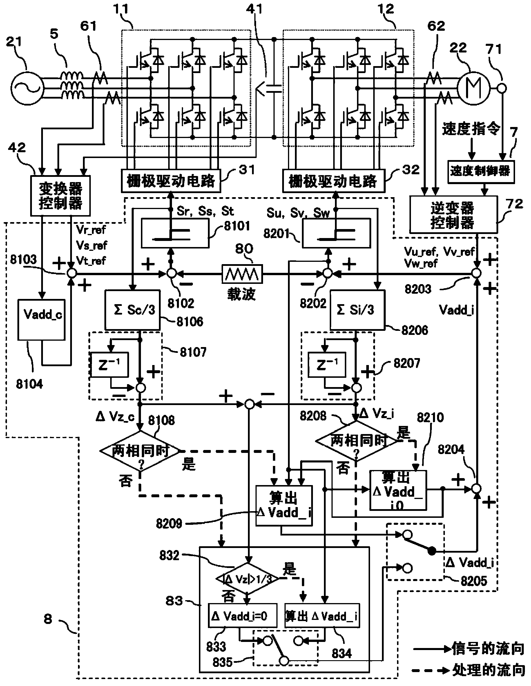
[0035] figure 1 The structure of the first embodiment of the present invention is shown. figure 1 The power conversion device can be used, for example, to drive an elevator or the like. figure 1 power conversion device, with Figure 12 As in the power conversion device shown, the AC power from the AC power source 21 is converted into DC power by the converter 11 as the conversion circuit, and the DC power smoothed by the smoothing capacitor 41 is passed through the inverter 12 (the conversion circuit) as the conversion circuit. ) into alternating current with variable voltage and frequency, and the converted alternating current is supplied to the motor 22 . In addition, in figure 1 In the example of , the DC circuit has a first potential and a second potential. In addition, the AC of the power supply 21 and the motor 22 are both multi-phase AC and three-phase AC respectively. A filter circuit 5 is connected between the power supply 21 and the inverter 11 . Each phase o...
no. 2 example
[0075] Figure 9 Shows the second embodiment of the present invention. The description of the same parts as those of the first embodiment will be omitted below, and only the different parts will be described. In the second embodiment, the carrier 801 of the converter 11 is set lower than the carrier 802 of the inverter 12 . Also in this case, the same effect as that of the first embodiment can be obtained. When the converter 11 side with a low carrier frequency corrects it based on the switching timing of the inverter 12 side, the number of switching times becomes larger than the number of switching times determined by the carrier wave 801 , which may lead to an increase in loss. Therefore, the correction voltage ΔVadd_i is superimposed only on the side of the inverter 12 with a high carrier frequency according to the switching timing of the converter 11 . In this case, the frequency of the carrier wave 802 on the side of the inverter 12 is higher than that of the first emb...
no. 3 example
[0077] Figure 10 A third embodiment of the present invention is shown. The following is only for figure 1 The different sections are explained. In the above-mentioned first and second embodiments, the superposition correction is only performed on the inverter 12 side to reduce the zero-phase current, but in this embodiment, the same correction as that on the inverter side is also performed on the converter 11 side fix. That is to say, when there are two or more switches on the side of the inverter 12 performing switching operations in the same potential change direction, if the judgment result of the judging part 8208 is positive, in the superimposed voltage calculation part 8109, the superimposed voltage The calculation section 8209 calculates the correction voltage ΔVadd_c on the converter 11 side in the same manner. This correction voltage ΔVadd_c is selected by the same selection section 8105 as the selection section 8205 . Thereafter, the correction voltage ΔVadd_c...
PUM
 Abstract
Description
Claims
Application Information
 - R&D
- Intellectual Property
- Life Sciences
- Materials
- Tech Scout
- Unparalleled Data Quality
- Higher Quality Content
- 60% Fewer Hallucinations
Browse by: Latest US Patents, China's latest patents, Technical Efficacy Thesaurus, Application Domain, Technology Topic, Popular Technical Reports.
© 2025 PatSnap. All rights reserved.Legal|Privacy policy|Modern Slavery Act Transparency Statement|Sitemap|About US| Contact US: help@patsnap.com


