Current transformer saturation detecting method

A technology of current transformers and detection methods, which is applied in the direction of instruments, measuring electronics, measuring devices, etc., can solve the problems of large high-order harmonics, inaccurate judgment, inaccurate detection, etc., and achieve the effect of improving sensitivity

Active Publication Date: 2014-01-22
长园深瑞继保自动化有限公司
View PDF5 Cites 34 Cited by
  • Summary
  • Abstract
  • Description
  • Claims
  • Application Information

AI Technical Summary

Problems solved by technology

[0006] Although the above method can judge CT saturation, it cannot accurately detect the time difference between the differential current and the braking current when the external fault is seriously saturated; for the harmonic ratio method, the time difference current is extremely saturated when the external fault is seriously saturated. It is relatively small and cannot be accurately judged. When the fault short-circuit current in the area is large, large high-order harmonics will also be generated, which will block the protection by mistake and cause refusal to operate; while the wavelet transform method is sensitive to waveforms and is affected by line harmonics. Content and DC component have a greater influence
None of the above CT saturation detection methods can accurately detect CT saturation, neither can effectively ensure that the differential protection does not malfunction when an external fault occurs, and will also reduce the sensitivity of the differential protection when an internal fault occurs

Method used


Image

  • Current transformer saturation detecting method
  • Current transformer saturation detecting method
  • Current transformer saturation detecting method

Examples


Embodiment Construction

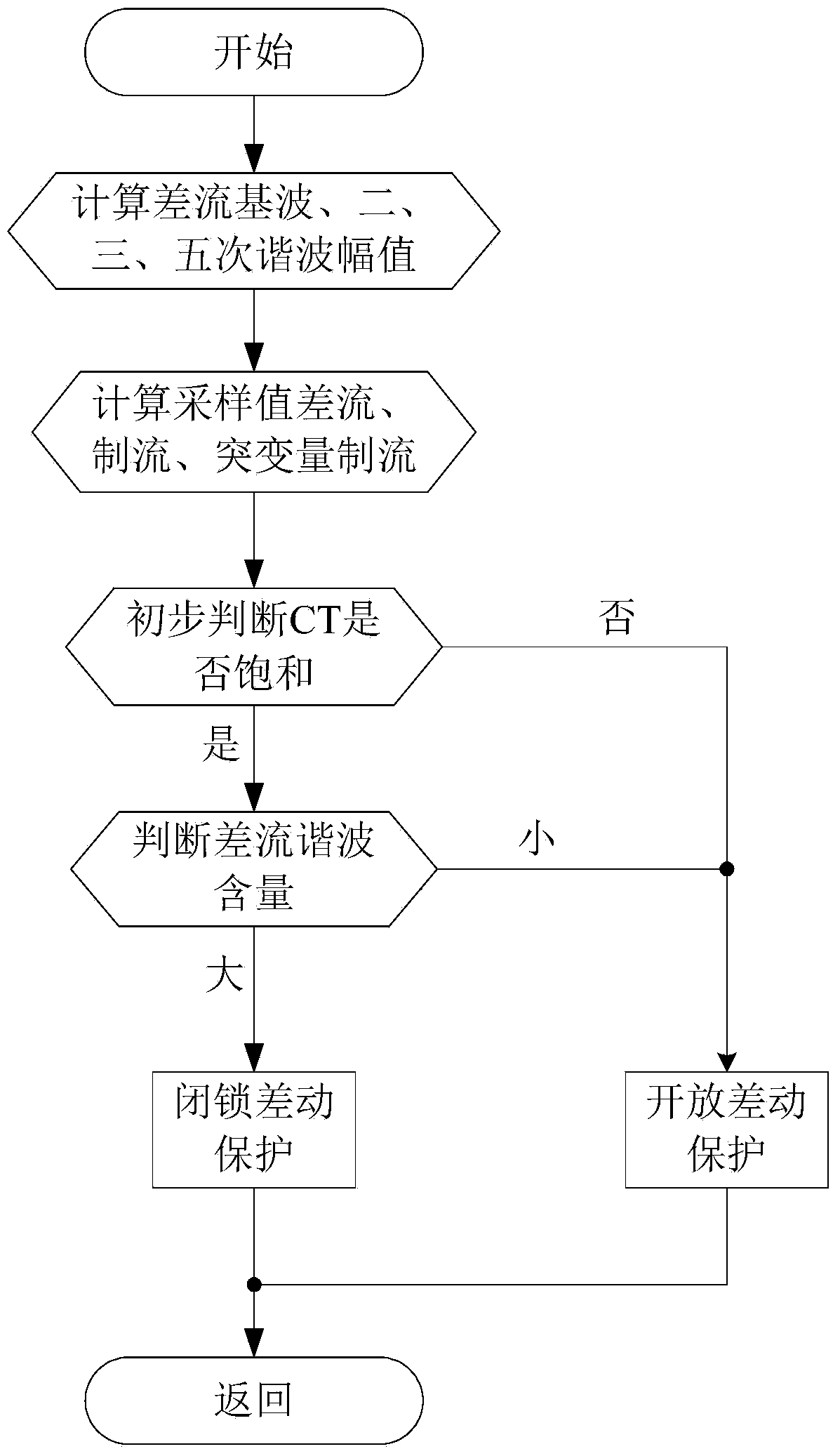
[0023] The present invention will be described in further detail below in conjunction with the accompanying drawings and embodiments. like figure 1 As shown, the current transformer saturation detection method of the present invention comprises the following steps:

[0024] 1. Calculating the current fundamental wave difference current amplitude I at the installation place of the protection device d , second harmonic differential current amplitude I 2d , The third harmonic differential current amplitude I 3d and the fifth harmonic differential current amplitude I 5d .

[0025] The relay protection device (protection device) installed at the head end of the transmission line on this side collects 24 points per cycle, collects the current of each phase of the first section of the transmission line on this side, and the current of each phase on the opposite side at the end of the transmission line. The Fourier algorithm calculates the fundamental wave I of each phase current...


PUM


Abstract

The invention discloses a current transformer saturation detecting method and aims at solving the technical problem of improving the saturation detection accuracy of a current transformer. The current transformer saturation detecting method comprises the following steps: calculating the amplitude values of Im, I2m, I3m, I5m, In, I2n, I3n and I5n by a relay protection device; calculating according to the following equations: Id = Im + In, I2d = I2m + I2n, I3d = I3m + I3n, and I5d = I5m + I5n by the relay protection device; calculating according to the following equations: id = imp + inp, ir = imp - inp, and dir = | (imp - im ( p - N ) ) | + | ( inp - in ( p - N ) ) | by the relay protection device; meeting the following conditions: 1) dir > 0.8in, 2) the sample number meeting ir > 0.8in is smaller than N, 3) the sample number meeting id > 0.8in is smaller than 3, and the difference between the sample number meeting the condition 2) and the sample number meeting the condition 3) is bigger than 3; failing to meet the condition: I2d + I3d + I5d < 0.15Id; and judging that the current transformer is saturated. Compared with the prior art, the current transformer saturation detecting method has the advantages that the method not only ensures that false differential protection operation is not carried out during external major faults with CT (Current Transformer) saturation, but also can improve differential protection sensitivity during internal faults with CT saturation through the judgment of time difference between differential current and brake current and the harmonic properties of the differential current in combination with harmonic properties during the CT saturation.

Description

technical field [0001] The invention relates to a relay protection method of a power system, in particular to a method for detecting the saturation of a current transformer. Background technique [0002] The principle of current differential protection is simple and reliable, and has been widely used in the main protection of components such as buses, generators, and transformers in power systems. With the development of optical fiber communication technology, more and more high-voltage, ultra-high voltage and ultra-high voltage transmission lines use optical fiber current differential protection as the main protection of the line. [0003] The current transformer CT is an important device of various relay protection devices. Whether it can truly transmit and change the primary current in the transient process of the power system plays a decisive role in the correct operation of the relay protection device. [0004] Due to the existence of line impedance in high-voltage, ul...

Claims


Application Information

Patent Timeline
Patent Type & Authority Applications(China)
IPC IPC(8): G01R31/00
Inventor 刘宏君俞伟国宁涛高小全赵亮周阳
Owner 长园深瑞继保自动化有限公司
Why Eureka
Try Eureka