Optical module

A light module and light source technology, applied in the field of light modules, can solve the problems of high manufacturing cost, side lighting, daytime driving lights, flash or low beam or blocked low beam distribution, cost coordination and adjustment, etc., to achieve The effect of low cost, saving structural space and saving material cost

Active Publication Date: 2014-01-22
AUTOMOTIVE LIGHTING REUTLINGEN GMBH
View PDF7 Cites 16 Cited by
  • Summary
  • Abstract
  • Description
  • Claims
  • Application Information

AI Technical Summary

Problems solved by technology

[0005] However, this known solution has the problem that at least a plurality of light modules must be combined with one another and coordinated with one another in order to provide a uniform distribution of the illuminating light and in order to achieve a glare-free high beam of several headlights
This requires complex coordination and adjustment of the individual components, which can lead to high manufacturing costs
Furthermore, there is the problem of integrating other light functions, such as side lighting, daytime running lights, flashing lights or dipped beams or blocked dipped beam distributions, into such complex arrangements.

Method used


Image

  • Optical module
  • Optical module
  • Optical module

Examples


Embodiment Construction

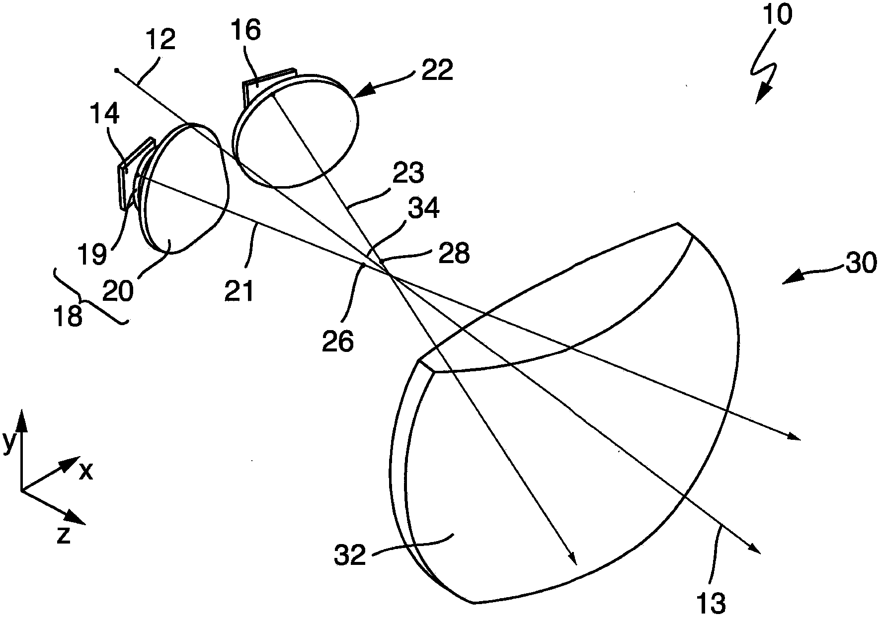
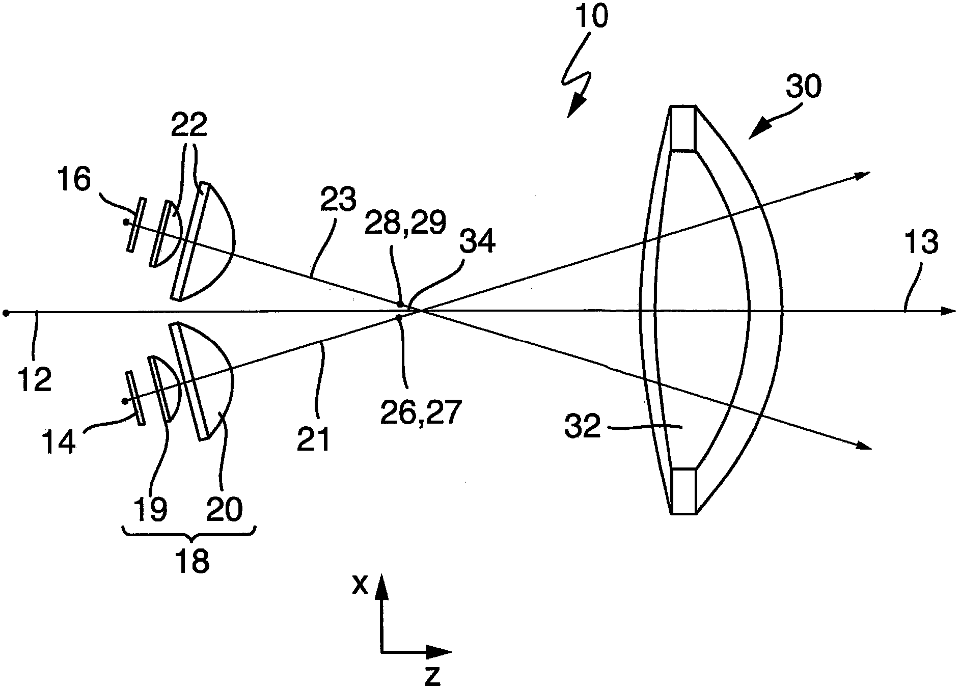
[0057] figure 1 A light module 10 according to the invention is shown, which can be used, for example, in motor vehicle headlights for high beams. For the light module 10 , an optical axis 12 is defined, which lies in a main radiation direction 13 . For better illustration, the light module 10 is shown without a housing, wherein any desired type of housing can of course be provided.

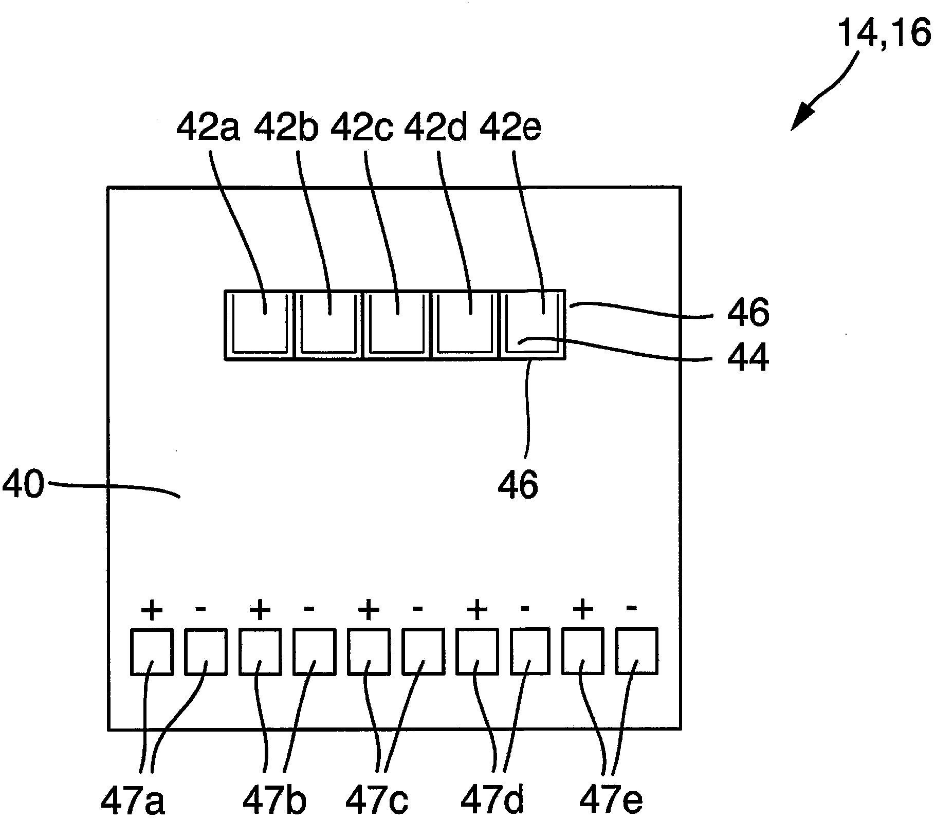
[0058]The optical module 10 has a first semiconductor light source 14 and a second semiconductor light source 16, further referring to image 3 and 7 Describe its precise design in detail. In each case, each semiconductor light source has a plurality of light-emitting diodes (LEDs) arranged in groups, wherein each LED of each semiconductor light source 14 or 16 is configured such that the source light segment corresponding to the respective LED can be emitted .

[0059] The first semiconductor light source 14 is associated with a first primary optics device 18 so that the source light segmen...


PUM


Abstract

A light module having a first and a second primary optics device wherein the individual LEDs of a first and a second semiconductor light source can be reproduced as real intermediate images on an intermediate image surface, wherein an intermediate image assigned to the first semiconductor light source is overlapping with at least one intermediate image assigned to a second semiconductor light source, and that a secondary optics device is arranged in such a way that the intermediate images can be projected as assigned light beam segments of the light beam distribution.

Description

technical field [0001] The invention relates to a light module according to the preamble of claim 1 for a lighting device, in particular for a motor vehicle. Such light modules are used as high beam modules in motor vehicle headlights. Background technique [0002] A high uniformity of the irradiating light distribution is generally desired here. In principle, strip-shaped areas of the light distribution with mutually different light intensities should be avoided since these areas can be perceived as disturbances. On the other hand, the high beam in motor vehicle headlights should be realized as glare-free as possible. [0003] For this purpose, EP 2 280 215 A2 describes a motor vehicle headlight having a plurality of LED light source modules for emitting light in approximately parallel radiation directions. Each LED light source module includes one or more LEDs that emit a source light segment. The LED light source module also includes a primary optical element for conv...

Claims


Application Information

Patent Timeline
Patent Type & Authority Applications(China)
IPC IPC(8): F21S8/10F21V5/04F21V19/00F21V14/08F21V14/02F21W101/10F21Y101/02
CPCF21S48/1258F21V5/08F21S48/1159F21S48/1747F21S41/143F21S41/147F21S41/255F21S41/26F21S41/663F21S41/153F21S41/151
Inventor 沃尔夫冈·霍夫尔德
Owner AUTOMOTIVE LIGHTING REUTLINGEN GMBH
Why Eureka
Try Eureka