


Quick Research
Generate reliable direction feasibility study reports for your R&D in just a few steps.

Technical Q&A
Discover and master advanced knowledge NOW. Basics, ideas, possibilities, all at once.

Find Solutions
As an expert in R&D theories, this can generate solutions to your technical problems instantly.

Evaluate Feasibility
Analyze your overall solution with one click, know your potential R&D risks in advance.

Monitor Landscape
Get weekly tech updates, stay abreast of the latest tech innovations and key insights.
Glass block manufacturing device and method, glass forming product and optical component manufacturing method
A technology for manufacturing devices and manufacturing methods, applied to glass manufacturing equipment, glass molding, glass pressing, etc., which can solve problems such as poor shape and texture quality of glass blocks, and achieve the effects of preventing damage and inhibiting movement
- Summary
- Abstract
- Description
- Claims
- Application Information
AI Technical Summary
Problems solved by technology
Method used
Image

Examples
no. 2 Embodiment approach
[0100] In the example of the above-mentioned first embodiment, the cam plates 70, 80 and the spring plate 86 are used to control the swing of the pod 10 (molding die 12), but other driving mechanisms such as a gear mechanism, a link mechanism, and a hydraulic mechanism may also be used. Shake control for pods. In the example of the second embodiment of the present invention described next, the pod swing is controlled using a gear mechanism. In the following description of the second embodiment, points different from the first embodiment will be mainly described, and the same or similar reference numerals will be used for the same or similar components as those of the first embodiment, and detailed description thereof will be omitted.
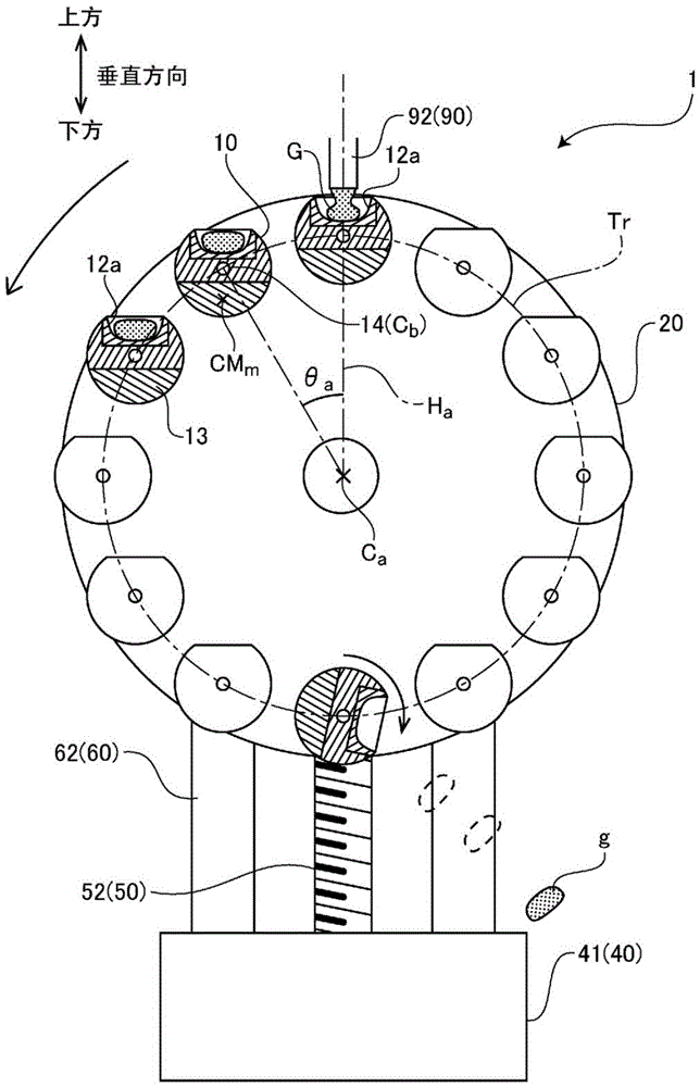
[0101] Figure 7 It is a front view of the glass gob shaping|molding apparatus 100 of 2nd Embodiment of this invention. Like the first embodiment, twelve pods 110 are attached at intervals of 30° around the rotation central axis Ca on the peri...
no. 3 Embodiment approach
[0111] In the examples of the first and second embodiments described above, a vertically placed turntable was used, but the present invention can also be applied to an apparatus in which the turntable is placed horizontally. Next, a description will be given of a third embodiment of the present invention using a horizontally placed turntable.
[0112] Figure 11 It is a top view of a glass gob forming apparatus 200 according to a third embodiment of the present invention, Figure 12 for its side view ( Figure 11 View in the direction of arrow I). In the present embodiment, the rotary motor 30 and the disc-shaped rotary table 220 are arranged horizontally (that is, the rotation central axis Ca faces the vertical direction).
[0113] The glass block forming apparatus 200 includes an elevator 250 whose driving device moves up and down as a whole; The rotary electric machine 30 is attached to the upper surface of the central portion of the chassis 242 , and the rotary table 2...
PUM
 Abstract
Description
Claims
Application Information
 - R&D Engineer
- R&D Manager
- IP Professional
- Industry Leading Data Capabilities
- Powerful AI technology
- Patent DNA Extraction
Browse by: Latest US Patents, China's latest patents, Technical Efficacy Thesaurus, Application Domain, Technology Topic, Popular Technical Reports.
© 2024 PatSnap. All rights reserved.Legal|Privacy policy|Modern Slavery Act Transparency Statement|Sitemap|About US| Contact US: help@patsnap.com