Centrifugal friction coupler

A coupling and centrifugal technology, applied in clutches, automatic clutches, shaft couplings, etc., can solve problems such as danger, inability to meet the transmission requirements of high-power mechanical equipment, and inability to adjust centrifugal force

Inactive Publication Date: 2014-01-15
XUZHOU ZHIDIAN ELECTROMECHANICAL EQUIP
View PDF0 Cites 0 Cited by
  • Summary
  • Abstract
  • Description
  • Claims
  • Application Information

AI Technical Summary

Problems solved by technology

However, most of the current centrifugal friction couplings are equipped with a cylinder with a centrifugal block on the passive half coupling. When the active half coupling rotates, the centrifugal block will be tightly pressed against the passive half due to centrifugal force. The inner circumference of the coupling cylinder, but because the centrifugal block is limited in the cylinder, the centrifugal force cannot be adjusted, the friction surface cannot be increased, and the transmission power is small, so it cannot meet the transmission requirements of high-power mechanical equipment; at the same time, due to the The friction of the centrifugal block during use can easily cause the surface temperature to be too high. If it is used in the mine, it will easily cause a gas explosion, which is very dangerous, and it will also affect its service life in the long run.

Method used


Image

  • Centrifugal friction coupler

Examples


Embodiment Construction

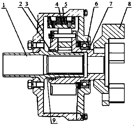
[0012] The present invention will be further described below in conjunction with the accompanying drawings.

[0013] Such as figure 1 As shown, a centrifugal friction coupling includes a driving coupling 8, a driven coupling 1, a connecting sleeve 9, a core 2, a centrifugal friction block 4, a bearing 6 and a housing 3, and the driving coupling 8 Connected with the driven coupling 1 through the connecting sleeve 9, the core 2 is located on the driven coupling 1, and the centrifugal friction block 4 is installed on the core 2, and the gap between the housing 3 and the driven coupling 1 A bearing 6 is installed at the place, and the number of the centrifugal friction blocks 4 is three, and the three centrifugal friction blocks 4 are evenly distributed on the core 2, and the centrifugal friction blocks 4 are provided with an antistatic wear-resistant material layer 5 .

[0014] Preferably, the bearing 6 is a copper sleeve bearing, which has the characteristics of high load capa...


PUM


Abstract

The invention discloses a centrifugal friction coupler. The centrifugal friction coupler comprises a driving coupling device, a driven coupling device, a connecting sleeve, a movement, centrifugal friction blocks, a bearing and a shell, wherein the driving coupling device is connected with the driven coupling device through the connecting sleeve, the movement is located on the driven coupling device, the centrifugal friction blocks are installed on the movement, the bearing is installed in the gap between the shell and the driven coupling device, the number of the centrifugal friction blocks is three, and the three centrifugal friction blocks are evenly distributed on the movement and provided with anti-static and anti-abrasion material layers. The centrifugal friction coupler has the advantages that centrifugal force can be adjusted in time due to the fact that the three centrifugal friction blocks are evenly distributed, and transmission requirements of large-power mechanical equipment are met; meanwhile, due to the fact that the anti-static and anti-abrasion material layers are arranged on the centrifugal friction blocks, danger caused by the rising of temperature of the surfaces of the centrifugal friction blocks can be avoided, and the service life is effectively prolonged.

Description

technical field [0001] The invention relates to a coupling, in particular to a centrifugal friction coupling. Background technique [0002] The coupling belongs to the category of mechanical general parts and is a part of the mechanical transmission device. Its main function is to connect the motor and the shaft of the working machine and transmit torque, and it can properly compensate the radial and vertical displacement of the two shafts caused by factors such as manufacturing and installation. axial error. For a long time, mining equipment belt conveyors and scraper conveyors have used hydraulic couplings. The hydraulic clutch is partially filled with a liquid medium in the inner cavity of the clutch. When the motor drives the clutch to rotate, the liquid medium impacts the turbine wheel blades of the clutch under the action of centrifugal force, thereby driving the output shaft to rotate. Since hydraulic clutches generally use oil or water as the force transmission med...

Claims


Application Information

Patent Timeline
Patent Type & Authority Applications(China)
IPC IPC(8): F16D43/18F16D43/21F16D7/02
Inventor 张庆
Owner XUZHOU ZHIDIAN ELECTROMECHANICAL EQUIP
Why Eureka
Try Eureka