
Installation layout structure of ventilation limit switch in gas turbine natural gas room

A travel switch, natural gas room technology, applied in mechanical equipment, machine/engine, pump control, etc., can solve the problems of weak output of ventilation fans in natural gas rooms, unable to operate the travel switch normally, and insufficient to overcome the outlet baffle, etc. Conducive to long-term safe and economical operation, reduction of gas turbine tripping accidents, and low cost

Active Publication Date: 2016-01-20
HUADIAN ELECTRIC POWER SCI INST CO LTD
View PDF4 Cites 0 Cited by
  • Summary
  • Abstract
  • Description
  • Claims
  • Application Information

AI Technical Summary

Problems solved by technology

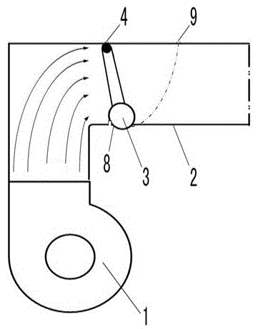
[0004] 1. In the case of a certain fan output, it is not enough to overcome the downward gravity of the outlet baffle to make the crank arm fully rise to the height of the top of the air duct, so that the travel switch installed on the upper part of the crank arm cannot operate normally.
[0005] 2. The instantaneous start-up of other high-power power-consuming auxiliary engines of the gas turbine may temporarily weaken the output of the ventilation fan in the natural gas room, causing the lifting height of the crank arm to drop for a short time and causing the travel switch to change to an abnormal state
[0006] 3. Slight air leakage at the joint of the ventilation pipe, increased frictional force after rust on the connecting shaft of the crank arm of the outlet baffle, and opening of the inlet door of the natural gas room may cause the travel switch to change to an abnormal state

Method used


Image

  • Installation layout structure of ventilation limit switch in gas turbine natural gas room
  • Installation layout structure of ventilation limit switch in gas turbine natural gas room

Examples


Embodiment Construction

[0019] The present invention will be further described in detail below in conjunction with the accompanying drawings and examples. The following examples are explanations of the present invention and the present invention is not limited to the following examples.

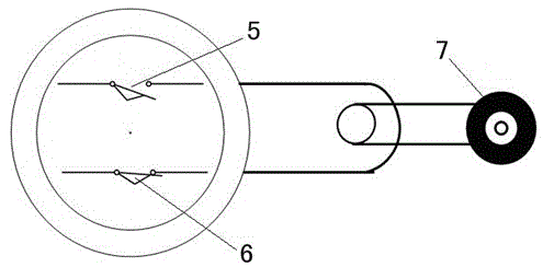
[0020] see figure 1 with figure 2 , The embodiment of the present invention includes a natural gas room fan 1, an air duct pipe 2, a travel switch 3, and an outlet baffle crank arm 4.

[0021] The air duct pipe 2 is connected with the fan 1 in the natural gas room, and an air duct is formed in the air duct pipe 2 . The lower part of the air duct pipe 2 is provided with a travel switch installation position 8, and the travel switch installation position 8 is located on the lifting path of the outlet baffle crank arm 4.

[0022] The travel switch 3 has a normally open node 5 , a normally closed node 6 , and an actuating crank arm 7 . The action crank arm 7 is connected with the normally closed node 6 . The travel...


PUM


Abstract

The invention relates to a ventilation travel switch installing and arranging structure of a gas turbine natural gas chamber. The ventilation travel switch installing and arranging structure comprises a natural gas chamber draught fan, an air flue pipe, a travel switch and an outlet baffle connecting lever. The air flue pipe is connected with the natural gas chamber draught fan, an air flue is formed in the air flue pipe, and the air flue pipe is provided with a travel switch installing position which is located on the lifting path of the outlet baffle connecting lever. The travel switch is provided with a normally-open node, a normally-close node and an action connecting lever. The ventilation travel switch installing and arranging structure is characterized in that the travel switch installing position is arranged on the lower portion of the air flue pipe, and the travel switch is located on the lower portion of the air flue pipe and on the travel switch installing position. The two ends of the normally-close node are connected with wires. The outlet baffle connecting lever is matched with the action connecting lever. The ventilation travel switch installing and arranging structure is reasonable in structural design, reliable in performance, easy to operate, convenient to use, practical and low in cost.

Description

technical field [0001] The invention relates to an installation arrangement structure of a ventilation travel switch between a gas turbine and a natural gas room. Background technique [0002] Gas turbines are currently recognized as environmentally friendly and efficient generating units around the world. In recent years, my country has introduced a large number of gas turbine combined cycle units similar to 9E gas turbines with natural gas inter-gas fans. [0003] The purpose of the complete set of fan equipment in the gas turbine natural gas room is to ventilate and prevent the explosion caused by the accumulation of natural gas. At present, the external ventilation travel switches of the gas turbine units with gas turbine natural gas room fans are all used in such as figure 2 The upper travel switch installation position 9 in the middle is installed, and the travel switch adopts the installation layout method of wiring at both ends of the normally open node. The origin...

Claims


Application Information

Patent Timeline
Patent Type & Authority Patents(China)
IPC IPC(8): F04D27/00
Inventor 李明张绍清刘战礼张跃中孙亮刘洋姚生龙贾宁波
Owner HUADIAN ELECTRIC POWER SCI INST CO LTD
Learn More