
Large-stroke high-precision Z-axis worktable with novel structure

A workbench and large-stroke technology, applied in the direction of manufacturing tools, machine tables/supports, large fixed members, etc., can solve problems such as difficult to achieve gravity balance, complex structure, lack of sensor monitoring, etc., achieve real-time guarantee of state adjustment, reduce A The effect of Baye error

Active Publication Date: 2014-01-15
HUAQIAO UNIVERSITY
View PDF6 Cites 6 Cited by
  • Summary
  • Abstract
  • Description
  • Claims
  • Application Information

AI Technical Summary

Problems solved by technology

[0003] In view of this, the present invention aims at the deficiencies in the prior art, and its main purpose is to provide a large-stroke high-precision Z-axis table with a novel structure, which can effectively solve the Abbe error of the existing Z-axis table. Problems that cannot be controlled but cannot meet the requirements of micro-nano measurement and micro-nano processing
[0004] Another object of the present invention is to provide a large-stroke high-precision Z-axis workbench with a novel structure, which can effectively solve the problems that the existing Z-axis workbench is difficult to achieve gravity balance, has a complicated structure, and makes the drive control difficult to be uniform and stable.
[0005] Another object of the present invention is to provide a large-stroke high-precision Z-axis table with a novel structure, which can effectively solve the problem that the existing Z-axis table lacks necessary sensor monitoring

Method used


Image

  • Large-stroke high-precision Z-axis worktable with novel structure
  • Large-stroke high-precision Z-axis worktable with novel structure
  • Large-stroke high-precision Z-axis worktable with novel structure

Examples


Embodiment Construction

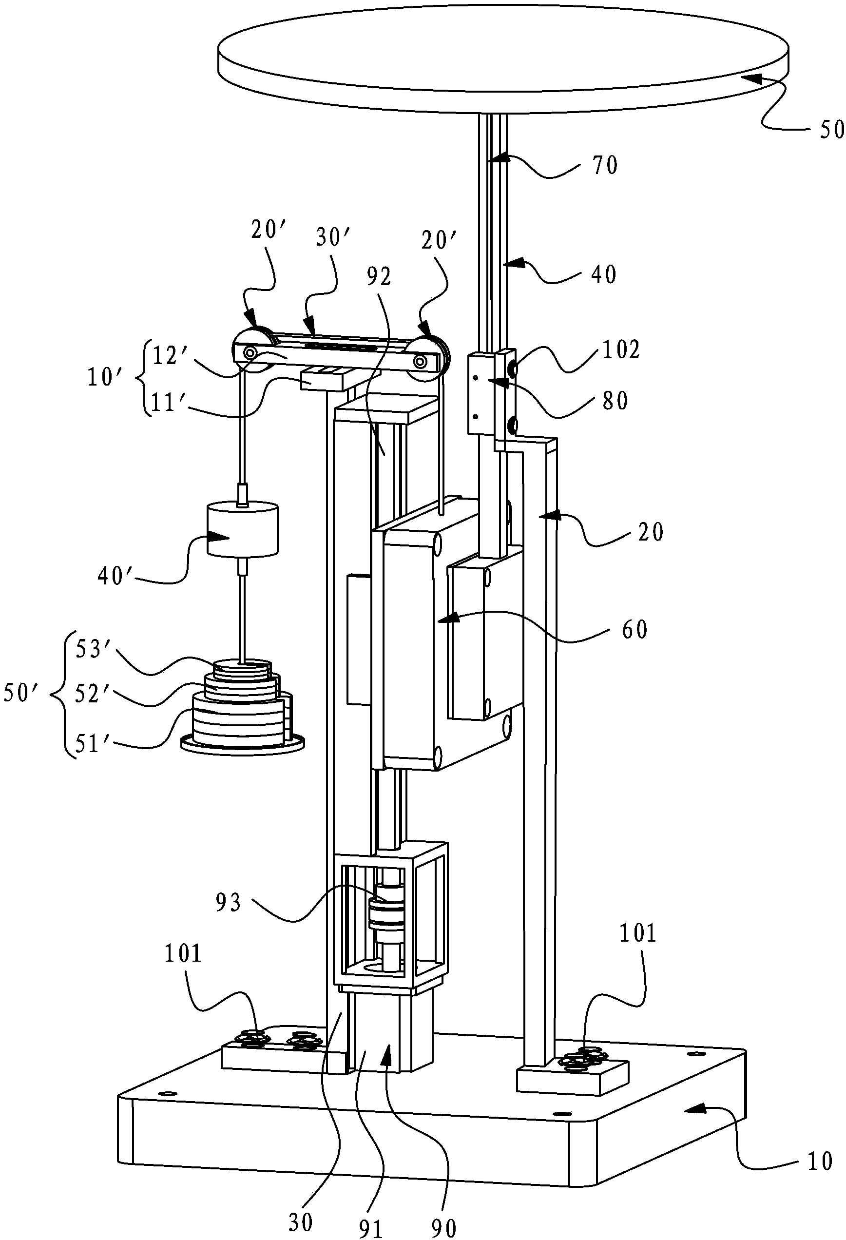
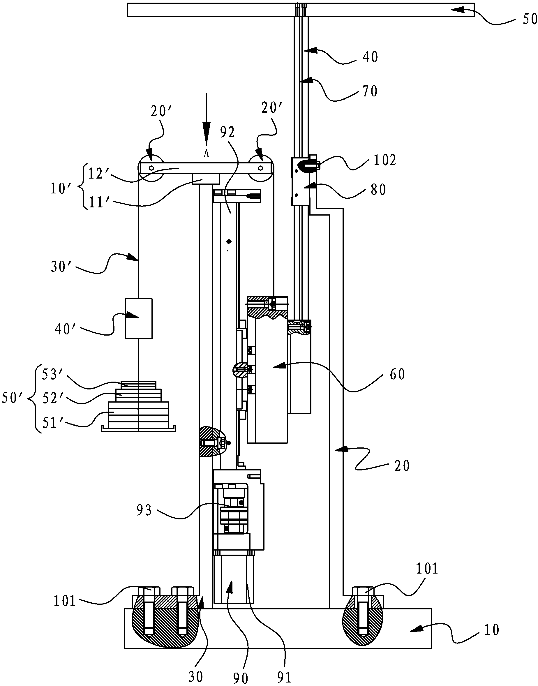
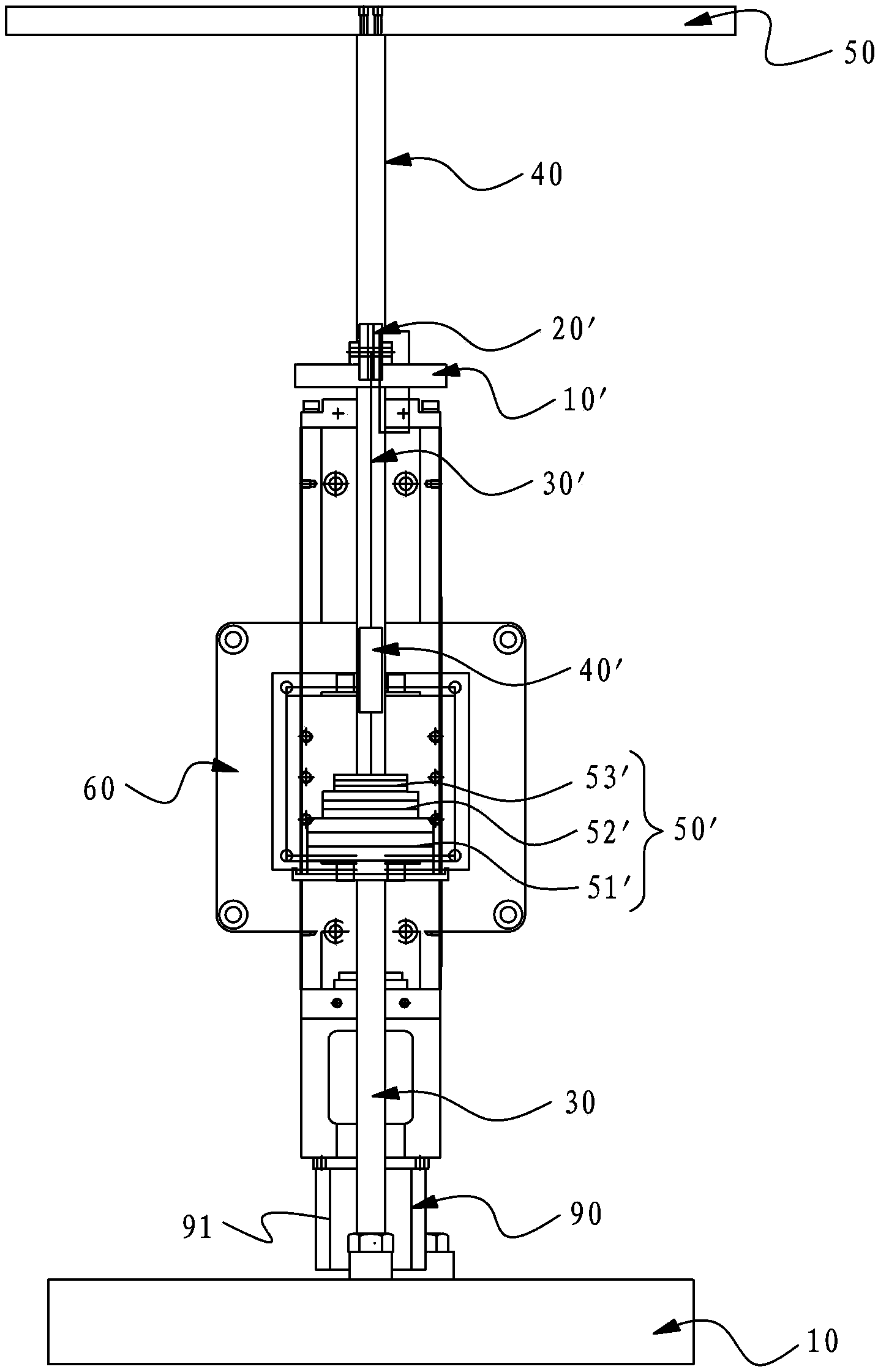
[0039] Please refer to Figure 1 to Figure 5 As shown, it shows the specific structure of the preferred embodiment of the present invention, including a base 10 , a first support 20 , a second support 30 , a movable support rod 40 , a workbench 50 and a precision movable positioning platform 60 .

[0040] Wherein, the first bracket 20 and the second bracket 30 are all arranged on the base 10; in this embodiment, the first bracket 20 and the second bracket 30 are both L-shaped brackets, and the first bracket 20 and the second bracket 30 are all fixed on the base 10 by screws 101, not limited thereto.

[0041] The movable support rod 40 extends vertically, and the movable support rod 40 can be arranged on the first support 20 up and down. The movable support rod 40 is fixed with a vertically extending grating scale 70. There is a grating reading head 80 , which is fixed on the first bracket 20 by slotted flat end set screws 102 .

[0042] The workbench 50 is fixed on the upper...


PUM


Abstract

The invention discloses a large-stroke high-precision Z-axis worktable with a novel structure. The worktable comprises a base, a first support, a second support, a movable supporting rod, a worktable body and a precise movable positioning table. The first support and the second support are arranged on the base, the movable supporting rod is arranged on the first support in an upward and downward movable mode, the movable supporting rod is fixedly provided with a grating ruler extending vertically, the first support is provided with a grating reading head, the precise movable positioning table is arranged on the second support in an upward and downward movable mode, the lower end of the movable supporting rod is fixedly connected with the precise movable positioning table, and a drive device is arranged on the precise movable positioning table. Due to the fact that the center of the worktable body, the center of the grating ruler, the center of the grating reading head and the center of the precise movable positioning table are located on the same line, zero abbe errors of a system can be achieved theoretically, abbe errors of the system are reduced to the largest extent, and micro-nano measuring and micro-nano processing requirements can be met.

Description

technical field [0001] The invention relates to the technology in the field of precision mechanical structure design, in particular to a large-stroke high-precision Z-axis workbench with a novel structure. Background technique [0002] In the fields of micro-machinery, ultra-precision machining, micro-assembly, semiconductor device manufacturing, and nanotechnology, high-precision positioning and very fine motion are required, so micro-displacement drive technology has become a key technical support for these fields. At present, in many applications, a Z-axis worktable with a stroke of tens of millimeters and a positioning accuracy of nanometers is required. Most of the Z-axis worktables that meet the large range and high precision adopt multi-stage drive. The large stroke is driven by a stepping motor, the stroke is large but the positioning accuracy is not high; and then the micro-drive of piezoelectric ceramics is used to achieve high-precision positioning. Therefore, i...

Claims


Application Information

Patent Timeline
Patent Type & Authority Applications(China)
IPC IPC(8): B23Q1/46B23Q11/00B23Q17/00
CPCF16F15/28F16M11/28
Inventor 范伟金花雪余卿叶瑞芳
Owner HUAQIAO UNIVERSITY
Learn More