
Fuel Injection Control System for Internal Combustion Engine

A fuel injection and control system technology, applied in fuel injection devices, charging systems, engine control, etc., can solve problems such as poor discharge of high-pressure fuel pumps, poor discharge of high-pressure fuel pumps, fuel injection systems, etc.

Active Publication Date: 2016-02-17
TOYOTA JIDOSHA KK
View PDF6 Cites 0 Cited by
  • Summary
  • Abstract
  • Description
  • Claims
  • Application Information

AI Technical Summary

Problems solved by technology

[0013] In order to solve the above-mentioned problems, in the fuel injection control system of an internal combustion engine including a low-pressure fuel pump and a high-pressure fuel pump, when a discharge failure of the high-pressure fuel pump is detected, it is judged whether or not it occurs after increasing the discharge pressure of the low-pressure fuel pump. The discharge failure of the high-pressure fuel pump is detected, and in the case where the discharge failure of the high-pressure fuel pump occurs, it is determined that the fuel injection system including the high-pressure fuel pump has malfunctioned

Method used


Image

  • Fuel Injection Control System for Internal Combustion Engine
  • Fuel Injection Control System for Internal Combustion Engine
  • Fuel Injection Control System for Internal Combustion Engine

Examples


Embodiment 1

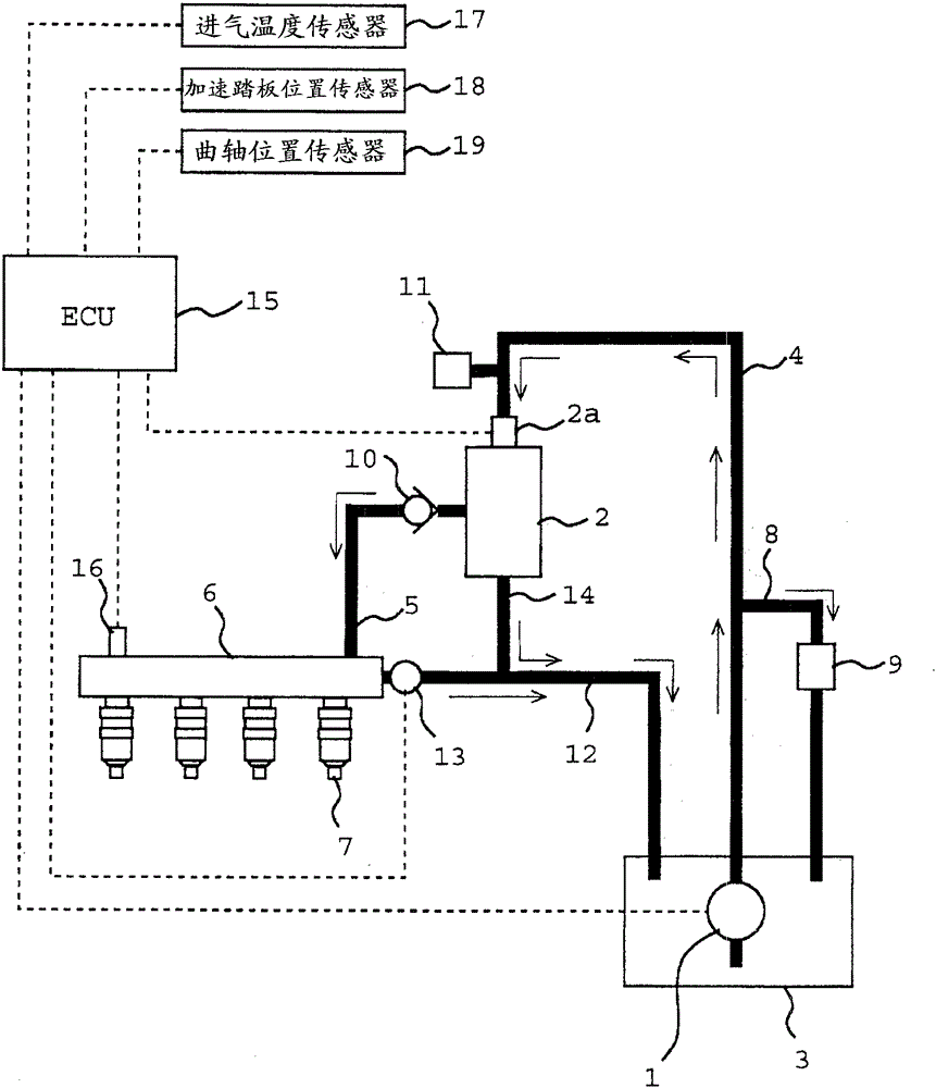
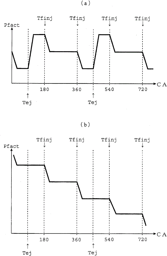
[0041] First, based on Figure 1 to Figure 4 A first embodiment of the present invention will be described. figure 1 It is a diagram showing a schematic configuration of a fuel injection control system for an internal combustion engine according to the present invention. figure 1 The fuel injection control system shown is a fuel injection control system suitable for a tandem four-cylinder internal combustion engine, and includes a low-pressure fuel pump 1 and a high-pressure fuel pump 2 . Wherein, the number of cylinders of the internal combustion engine is not limited to four, and may be more than five or less than three.

[0042] The low-pressure fuel pump 1 is a pump for pumping up fuel stored in the fuel tank 3, and is a turbo pump (scroll pump) driven by electricity. The fuel discharged from the low-pressure fuel pump 1 is guided to the fuel inlet of the high-pressure fuel pump 2 through the low-pressure fuel passage 4 .

[0043] The high-pressure fuel pump 2 is a pump...

Embodiment 2

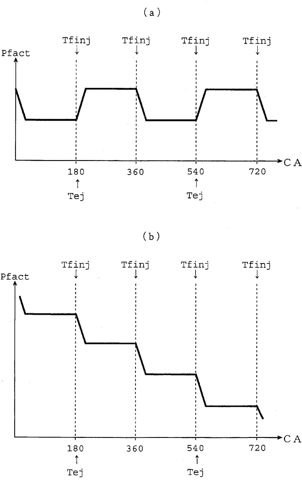
[0095] Below, based on Figure 5 to Figure 7 A second embodiment of the fuel injection control system for an internal combustion engine according to the present invention will be described. Here, configurations different from those of the first embodiment described above will be described, and descriptions of the same configurations will be omitted.

[0096] The difference between the aforementioned first embodiment and this embodiment is that there are multiple fuel injection systems including high-pressure fuel pumps. Figure 5 It is a diagram showing a schematic configuration of a fuel injection control system for an internal combustion engine in this embodiment. Figure 5 The fuel injection control system shown is a system suitable for a V-type 8-cylinder internal combustion engine. Wherein, the internal combustion engine is not limited to the V-type 8-cylinder, and may also be an internal combustion engine having a plurality of cylinder banks and each cylinder bank havi...


PUM


Abstract

An object of the present invention is to accurately detect failures in the fuel injection system including the high-pressure fuel pump in a fuel injection control system for an internal combustion engine including a low-pressure fuel pump and a high-pressure fuel pump. In order to solve this problem, in the fuel injection control system of an internal combustion engine provided with a low-pressure fuel pump and a high-pressure fuel pump, the present invention determines whether or not the failure occurs after increasing the discharge pressure of the low-pressure fuel pump when a discharge failure of the high-pressure fuel pump is detected. A discharge failure of the high-pressure fuel pump is detected, and when the discharge failure of the high-pressure fuel pump occurs, it is determined that the fuel injection system including the high-pressure fuel pump is malfunctioning.

Description

technical field [0001] The present invention relates to a fuel injection control system for an internal combustion engine including a low-pressure fuel pump that draws fuel from a fuel tank and a high-pressure fuel pump that boosts the pressure of fuel discharged from the low-pressure fuel pump. Background technique [0002] A control device for a direct-injection internal combustion engine has been proposed (for example, refer to Patent Document 1), which includes: a fuel injection valve for injecting fuel into a cylinder; a high-pressure pump for boosting the pressure of fuel drawn from a fuel tank; A high-pressure fuel passage through which discharged fuel is guided to a fuel injection valve; a fuel pressure prediction unit for predicting a fuel pressure in the high-pressure fuel passage through model calculation; a fuel pressure sensor for measuring a fuel pressure in the high-pressure fuel passage; An abnormality determination unit that determines that a high-pressure f...

Claims


Application Information

Patent Timeline
Patent Type & Authority Patents(China)
IPC IPC(8): F02M37/08F02M63/00
CPCF02M63/0245F02D41/3082F02D41/3845F02D41/3854F02D41/406F02M63/025F02D2041/224F02D2041/226F02D2200/0614F02D41/221Y02T10/40
Inventor 小岛进
Owner TOYOTA JIDOSHA KK
Learn More