Ultrasonic cmut with suppressed acoustic coupling to the substrate

An ultrasound and substrate technology, applied in the field of medical diagnostic ultrasound systems, can solve the problems of cMUT lack of commercial acceptance

Active Publication Date: 2014-01-08
KONINKLJIJKE PHILIPS NV
View PDF16 Cites 5 Cited by
  • Summary
  • Abstract
  • Description
  • Claims
  • Application Information

AI Technical Summary

Problems solved by technology

These issues have contributed to the lack of comme...

Method used


Image

  • Ultrasonic cmut with suppressed acoustic coupling to the substrate
  • Ultrasonic cmut with suppressed acoustic coupling to the substrate
  • Ultrasonic cmut with suppressed acoustic coupling to the substrate

Examples


Embodiment Construction

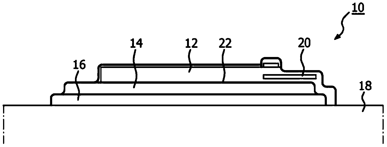
[0016] first reference figure 1 , shows a typical cMUT device 10 of the prior art through a cross-sectional view. The cMUT 10 includes a top electrode 12 composed of a conductive material. The top electrode is located on the diaphragm 22, or may itself comprise the diaphragm. In this illustration, the diaphragm is formed from a non-conductive material such as silicon nitride or silicon dioxide. The membrane is supported above the void or gap 14 by vertical supports at the lateral edges of the membrane. In this embodiment, the diaphragm spans the gap without touching the bottom of the gap bottom. In other embodiments, the diaphragm may be purposefully constructed or biased so that it operates in a collapsed mode, wherein the center of the diaphragm is in contact with the bottom of the gap. Conductor 20 couples electrical signals to or from top electrode 12 . Below the gap 14 is a bottom electrode 16 . Electrical connections to the bottom electrodes are made by the semicon...


PUM


Abstract

An array of cMUT cells are formed on individually isolated massive plates on a substrate. The mass of each plate provides an inertial force in opposition to the force and motion of transmission by the cell which reduces the resultant translation of motion in the plate. The reduction in motion results in less coupling of acoustic energy into the substrate and contamination of the signals of adjacent cMUT cells by lateral waves. The unwanted wave coupling into the substrate can be further damped by compliant or sparse periodic mounting of the massive plates on the substrate.

Description

technical field [0001] The present invention relates to medical diagnostic ultrasound systems and, in particular, to cMUT arrays with suppressed acoustic coupling of reverberant energy to the substrate of the cMUT (Capacitive Micromachined Ultrasound Transducer) array. Background technique [0002] MUTs, especially cMUTs, are ultrasonic transducer elements fabricated by semiconductor manufacturing techniques. Unlike conventional piezoelectric materials such as PZT, MUTs can operate through effects other than strictly piezoelectric. In the case of a cMUT, the diaphragm is vibrated in the manner of the diaphragm of a drum by the variable capacitance effect. Vibration of the diaphragm produces emitted ultrasonic energy. When receiving, the diaphragm is vibrated by the returned echo, and the capacitance change is sensed to detect the received echo signal. In my US patent 6328697 the figure 1 A typical cMUT cell is shown in . in this patent figure 2 An electrical diagram f...

Claims


Application Information

Patent Timeline
IPC IPC(8): B06B1/02G10K11/00
CPCG10K11/002B06B1/0292G01H11/06A61B8/4494
Inventor J·D·弗雷泽
Owner KONINKLJIJKE PHILIPS NV
Why Eureka
Try Eureka