A double switch thermostatic valve

A dual-switch, thermostatic valve technology, applied in valve devices, multi-way valves, mechanical equipment, etc., can solve the problems of easy freezing, no effect of antifreezing, cold water regulation, etc., and achieves novel and practical structure, simple manufacturing process, and guaranteed constant temperature. The effect of precision

Active Publication Date: 2019-09-27
崔荀
View PDF6 Cites 0 Cited by
  • Summary
  • Abstract
  • Description
  • Claims
  • Application Information

AI Technical Summary

Problems solved by technology

[0002] Most of the switches of the thermostatic valves currently on the market are set at the outlet of the mixed water. Because the valves store a lot of water and are under pressure when they are closed, they are easy to freeze in winter. In addition, because the switches of the thermostatic valves are located at the outlet of the mixed water Therefore, one-way valves must be added to the cold and hot water inlets to prevent problems such as water stringing after the valves are closed when the pressure difference between the cold and hot water inlets is too large.
[0003] In view of the above problems, the applicant once applied the four-hole ceramic valve core with dual switching function of cold and hot water in the utility model patent No. 200620000136.3 to the front of the hot and cold water inlet chamber of the thermostatic valve, thus solving the problem of thermostatic valve The backflow problem of stringing water after closing also saves the one-way valve at the cold and hot water inlet end of the thermostatic valve, but the patented product is limited in its appearance diversification due to its compact structure. no hint given
[0004] A horizontal structure of a thermostatic valve sold on the market using a double switch spool and a thermostatic spool solves the problems of water stringing, but it only realizes the switch and flow adjustment of the hot water in the double switch , the other set of switches is used to control the switch and flow adjustment of the mixed water outlet. Since the double switch knob does not adjust the flow of cold water at 90 degrees, the result affects the temperature adjustment accuracy of the thermostatic valve, especially It is more obvious when the flow rate is small. At the same time, because the water outlet is still under pressure when it is closed, it has no effect on antifreeze. In addition, due to the limitation of space in the product structure, the general standard is not used on the valve body. The size of the thermostatic spool assembly, but using the internal parts of the thermostatic spool for installation, which is not conducive to the mass production of the valve and the maintenance and disassembly of the thermostatic spool in the future

Method used


Image

  • A double switch thermostatic valve
  • A double switch thermostatic valve
  • A double switch thermostatic valve

Examples


no. 1 example

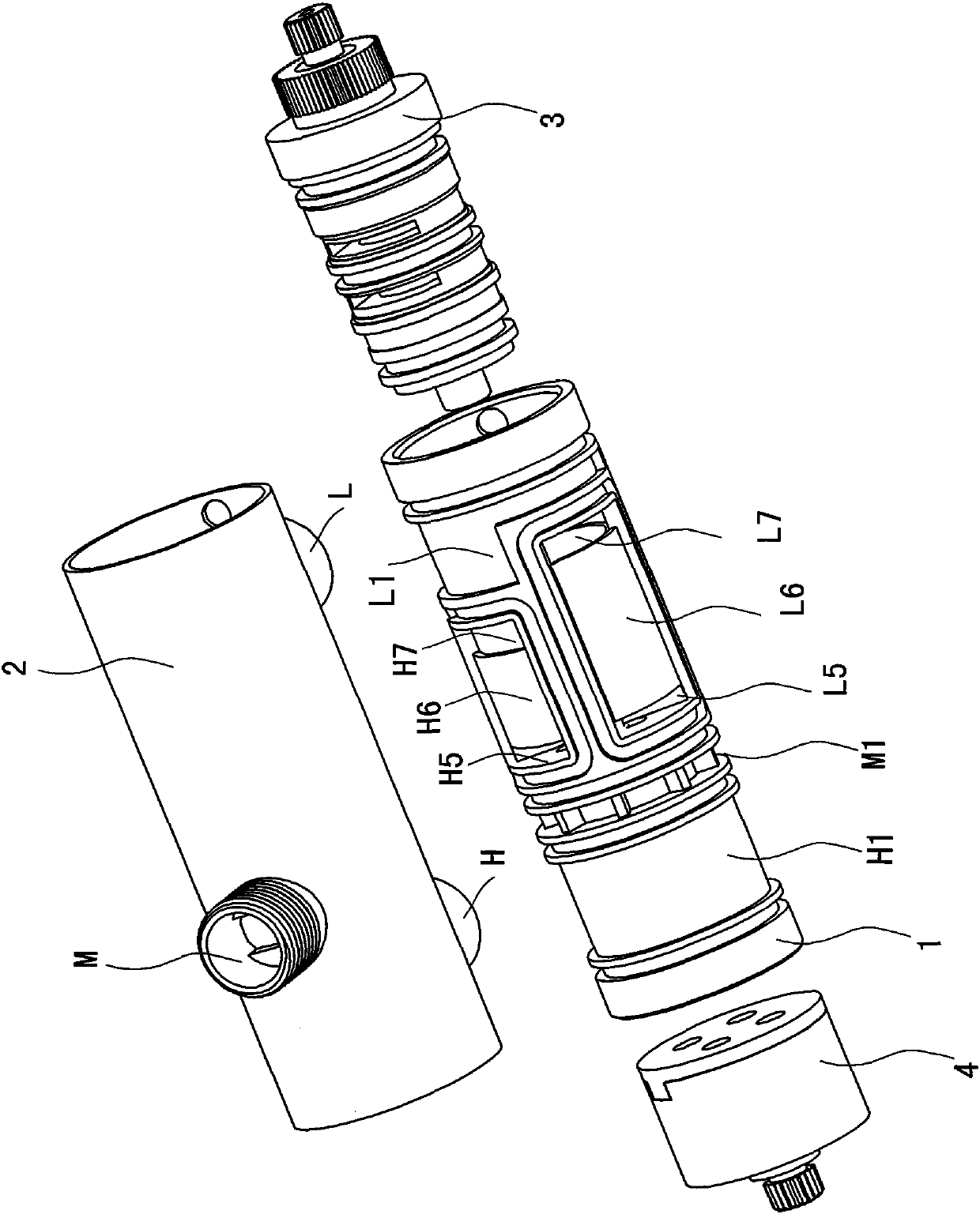
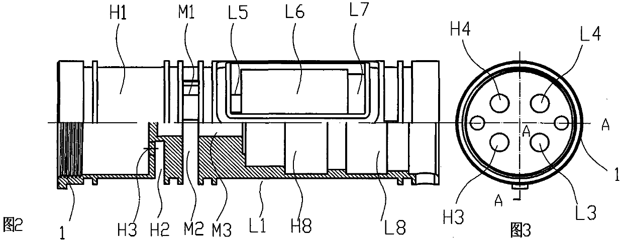
[0025] attached figure 1 It is an exploded schematic diagram of the three-dimensional structure of the present invention, which shows that it is composed of a columnar cavity 1, a valve body composed of an outer sleeve 2, a thermostatic valve core 3, and a double-switch valve core 4, wherein the thermostatic valve core 3 and the double-switch valve core 4 are all spool assemblies in the prior art, including the double switch knob and the temperature adjustment knob not shown in the figure, all of which are commonly used accessories in the prior art. image 3 It is the position diagram of the four holes for the inflow and outflow of hot and cold water on the bottom surface of the double switch valve core cavity of the columnar cavity 1 located at the left end (the switch of the thermostatic valve is generally set at the left end), and the attached figure 2 is attached image 3 Sectional view along line A-A, with Figure 4 , 5 And attached figure 2 The external and interna...

no. 2 example

[0033] attached Figure 6 and 7 As shown, on the basis of the above example, a partial annular concave cavity with the smallest area including the hot water inlet H and the hot water area outlet hole H2 is provided in a concave cavity corresponding to the hot water inlet H of the outer sleeve 2. The cavity, surrounded by the notch inlaid with the sealing ring, is the hot water zone H1. Outside the partial annular cavity, the channel connecting the water outlet hole L2 of the cold water zone and the cold water inlet hole L3 of the double switch is connected to the columnar cavity. A cooling water through hole L9 is provided on the outer peripheral surface of the body 1. This hole can overflow the cold water leading to the double switch valve core on the outer peripheral surface of the columnar cavity 1 and surround the partial annular concave cavity of the hot water zone H1. Thereby, the temperature of the outer sleeve 2 can be reduced to avoid scalding. In addition, this exa...

no. 3 example

[0035] attached Figure 8 and 9 As shown, another structure of the columnar cavity 1 is that only two O-rings are arranged at both ends on its outer peripheral surface, and between the two O-rings except the hot water chamber H6 and the cold water chamber L6 In addition, there are also two partial annular concave cavities, the hot water area H1 and the mixed water outlet area M1, which respectively include the hot water inlet H and the mixed water outlet M of the outer sleeve 2, and the rest of the outer peripheral surface is the cold water area L1. The cold water area L1 can surround the hot water area H1, thereby reducing the temperature of the outer sleeve 2 and avoiding burns.

[0036] As mentioned above, the double-switch thermostatic valve of the present invention is simple in process and low in cost. It is applied to the coaxial center structure of the horizontal thermostatic valve body and realizes double-switch and double-flow control in the true sense. The synchron...


PUM


Abstract

A dual-switch thermostatic valve comprises a thermostatic valve core (3), a dual-switch valve core (4), a dual-switch rotary knob, a temperature regulating rotary knob, and a valve body. The valve body is formed by a columnar cavity (1) and an outer sleeve (2). Cold and hot water inlets(L, H) and a mixed water outlet (M) are disposed on the outer sleeve (2), and are separately corresponding to cold and hot water inlet areas (L1, H1) and a water outlet area (M1) on the columnar cavity (1). The thermostatic valve core (3) and the dual-switch valve core (4) are fixedly disposed separately at the two ends of an inner cavity body of the columnar cavity (1), and the two valve cores are separately jogged with the thermostatic rotary knob and the dual-switch rotary knob to conduct temperature regulation and conduct switching on and switching off. The columnar cavity (1) can lead cold and hot water entering the outer sleeve (2) into the dual-switch valve core (4), and the cold and hot water are separately led to cold and hot water inlet cavities of the thermostatic valve core (3) after the dual-switch valve core (4) conducts switching on and off and flow regulation. The mixed water is regulated by means of the thermostatic valve core (3), so that the mixed water can outflow in a constant temperature. The dual-switch thermostatic valve solves the problem that when the thermostatic valve is closed, reverse flow and water mixing occur due to uneven pressure of cold water and hot water, and therefore a a one-way valve is not required, and the synchronous and even regulation of the cold water inflow and the hot water inflow is achieved, and the precision of the constant temperature of the thermostatic valve is ensured.

Description

technical field [0001] The invention relates to a double switch constant temperature valve, which is suitable for a water heater for bathing. Background technique [0002] Most of the switches of the thermostatic valves currently on the market are set at the outlet of the mixed water. Because the valves store a lot of water and are under pressure when they are closed, they are easy to freeze in winter. In addition, because the switches of the thermostatic valves are located at the outlet of the mixed water Therefore, one-way valves must be added to the cold and hot water inlets to prevent the disadvantages of water stringing after the valve is closed when the pressure difference between the cold and hot water inlets is too large. [0003] In view of the above problems, the applicant once applied the four-hole ceramic valve core with dual switching function of cold and hot water in the utility model patent No. 200620000136.3 to the front of the hot and cold water inlet chambe...

Claims


Application Information

Patent Timeline
Patent Type & Authority Patents(China)
IPC IPC(8): F16K11/22
Inventor 崔荀崔源湘
Owner 崔荀
Why Eureka
Try Eureka