A Stator Permanent Magnet Type Vernier Motor Structure with Reduced Positioning Force

A vernier motor, permanent magnet technology, applied in the magnetic circuit shape/style/structure, magnetic circuit static parts and other directions, can solve the problems of reduced positioning force, large positioning force, etc., to achieve high power density and increase manufacturing costs , the effect of improving power density

Active Publication Date: 2016-06-29
JIANGSU UNIV
View PDF6 Cites 0 Cited by
  • Summary
  • Abstract
  • Description
  • Claims
  • Application Information

AI Technical Summary

Problems solved by technology

[0004] The purpose of the present invention is to solve the problem of large positioning force in the existing magnetism-concentrating stator permanent magnet vernier motor, and propose a stator permanent magnet vernier motor structure that can reduce the positioning force to ensure that the positioning force is effectively reduced At the same time, the no-load back electromotive force and thrust output of the motor remain unchanged

Method used


Image

  • A Stator Permanent Magnet Type Vernier Motor Structure with Reduced Positioning Force
  • A Stator Permanent Magnet Type Vernier Motor Structure with Reduced Positioning Force
  • A Stator Permanent Magnet Type Vernier Motor Structure with Reduced Positioning Force

Examples


Embodiment Construction

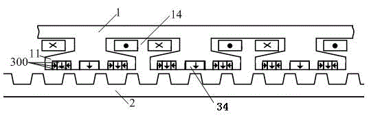
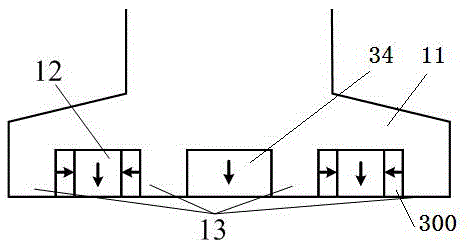
[0019] see figure 1 The structure of the stator permanent magnet vernier motor with reduced positioning force in the present invention includes two parts, the primary 1 and the secondary 2. There is an air gap between the primary 1 and the secondary 2, and the thickness of the air gap is selected according to the size and requirements of the motor. . The secondary 2 is formed by slotting the iron core to form a trapezoidal slot, the slotting on the primary 1 forms a slotted structure, and there is a slot 14 between two adjacent teeth on the primary 1, and the slot 14 is used to place the winding, and the winding is centralized or distributed Winding, groove 14 can adopt various groove types, select according to specific needs.

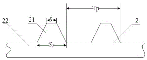
[0020] see figure 1 and figure 2 , a tooth of the secondary 1 includes a tooth 21 and a yoke 22, and the tooth 21 is trapezoidal in shape on the side opposite to the air gap. Teeth 21 near the air gap side width S 1 and pitch T p Ratio of K 1 =...


PUM


Abstract

The invention discloses a stator permanent magnet type vernier motor structure with reduced positioning force, which includes a primary and a secondary with an air gap between the primary and the secondary, and a plurality of Virtual groove and multiple virtual teeth, the number of virtual teeth N 1 and the number of virtual slots N 2 Yes , N 2 It is an odd number greater than 1; the fourth permanent magnet is embedded in the virtual slot in the middle, and the magnetic concentration module is embedded in the remaining virtual slots; the magnetization direction of the fourth permanent magnet is perpendicular to the motor movement direction and faces the air gap; the magnetic concentration The module is composed of three permanent magnets that are closely fitted in sequence. The magnetization direction of the middle permanent magnet is perpendicular to the motor movement direction and faces the air gap. The two permanent magnets on both sides are relatively magnetized and the magnetization direction is in line with the motor movement direction. The same; through the mutual cooperation of the permanent magnet and the magnetic gathering module, the positioning force can be reduced while ensuring that the performance indicators such as no-load back electromotive force, thrust output, and permanent magnet consumption are not affected.

Description

technical field [0001] The invention relates to a motor manufacturing technology and a primary permanent magnet motor positioning force technology, in particular to a stator permanent magnet vernier motor structure. Background technique [0002] The vernier motor has the characteristics of low speed and high torque, so it has good application scenarios in many occasions such as rail transit, ship propulsion, food processing and electric vehicles. At present, the permanent magnet vernier motor is mostly researched on the rotor permanent magnet motor, and the permanent magnet is placed on the rotor. During the operation of the motor, it will cause heat dissipation difficulties, and excessive temperature rise will cause permanent magnet loss. magnetism, causing the motor to malfunction. Stator permanent magnet motors place both permanent magnets and armature windings on the stator, and the rotor has no windings or permanent magnets. The structure is simple. The temperature ris...

Claims


Application Information

Patent Timeline
Patent Type & Authority Patents(China)
IPC IPC(8): H02K1/17H02K1/16H02K1/14
Inventor 吉敬华赵建兴赵文祥康梅
Owner JIANGSU UNIV
Why Eureka
Try Eureka