
Negative-pressure jointing bobbin

A bobbin and spinning-in technology, applied in the field of negative-pressure spinning bobbins, can solve the problems that yarn cannot be attached, yarn cannot contact with velvet tape, and affect automatic spinning-up rate, etc., so as to improve utilization rate and reduce labor intensity effect

Active Publication Date: 2014-01-01
CMT HICORP MACHINERY QINGDAO
View PDF10 Cites 2 Cited by
  • Summary
  • Abstract
  • Description
  • Claims
  • Application Information

AI Technical Summary

Problems solved by technology

[0003] One is that the currently used roving bobbins are affected by the position of the flyer’s presser palm during yarn spinning. When the position of the presser’s hand at the beginning of spinning does not reach the position of the bobbin velvet, the yarn cannot contact the velvet and the yarn will be in the roving. The part above the false twister of the machine hugs the end, resulting in a phenomenon that the roving end-up rate is not high, which cannot meet the requirements of the automatic end-up of the roving
[0004] Second, after a period of use of the currently used roving bobbin, a layer of fiber will be attached to the velvet tape, and even a large amount of static electricity will be generated. The automatic head spinning rate has resulted in the need for roving blockers to manually assist the head spinning, which cannot meet the requirements of automatic spinning
[0005] It can be seen from the above that the existing bobbin structure has determined that it cannot well meet the requirements of automatic spinning of automatic doffing roving frames, and needs further improvement and development.

Method used


Image

  • Negative-pressure jointing bobbin

Examples


Embodiment Construction

[0016] The present invention provides a negative pressure spinning bobbin. In order to make the purpose, technical solution and effect of the present invention clearer and clearer, the present invention will be further described in detail below. It should be understood that the specific embodiments described here are only used to explain the present invention, not to limit the present invention.

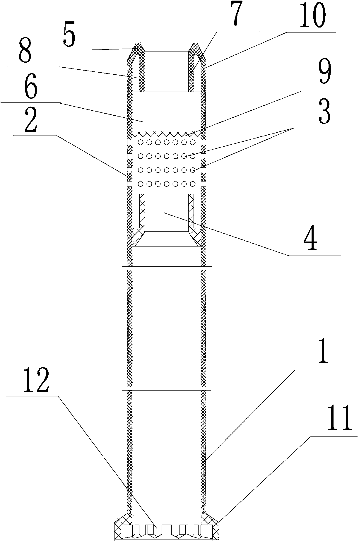
[0017] The invention provides a negative pressure yarn bobbin, such as figure 1 As shown, it includes a bobbin main body 1, and the bobbin main body 1 can be made of materials such as ABS. A plurality of negative pressure holes 3 are evenly arranged on the annular thread-in area 2 of the bobbin main body 1, and a negative-pressure chamber 4 is arranged in the bobbin main body 1 corresponding to the annular thread-in area 2, and the negative pressure The pressure hole 3 is connected with the negative pressure chamber 4, and the gas in the negative pressure chamber 4 is extracted to f...


PUM


Abstract

The invention discloses a negative-pressure jointing bobbin comprising a bobbin body. A plurality of negative-pressure holes are uniformly formed in an annular jointing area of the bobbin body. A negative-pressure cavity is formed inside the bobbin body in correspondence to the annular jointing area and is communicated with the negative-pressure holes. Air in the negative-pressure cavity is sucked to form negative pressure. A negative-pressure adsorption area is formed in the annular jointing area. Yarns are adsorbed in the annular jointing area under negative pressure. Negative pressure is formed in the negative-pressure cavity by a suction fan, and the negative-pressure holes in the wall of the bobbin body are used for adsorbing the yarns so as to facilitate automatic doffing jointing, so that the automatic doffing jointing rate is up to 100%, labor intensity is reduced, no yarns are left, and utilization rate of roving yarns is greatly increased.

Description

technical field [0001] The invention relates to a negative-pressure spinning bobbin. Background technique [0002] The roving bobbin used in the automatic doffing roving frame in the prior art has the same spinning principle, that is, a layer of velvet tape is wrapped on the top or bottom of the roving bobbin, and the yarn is pasted on the velvet tape when spinning starts. , to achieve the purpose of giving birth. The spinning rate of the roving is only about 80%, and manual assistance is needed, which increases the workload of the roving blockers, mainly in the following two aspects: [0003] One is that the currently used roving bobbins are affected by the position of the flyer’s presser palm during yarn spinning. When the position of the presser’s hand at the beginning of spinning does not reach the position of the bobbin velvet, the yarn cannot contact the velvet and the yarn will be in the roving. The part above the false twister of the machine hugs the end, resulting...

Claims


Application Information

Patent Timeline
IPC IPC(8): B65H75/28
Inventor 崔桂华王成吉刘增喜李建霞周春娟郭加阳
Owner CMT HICORP MACHINERY QINGDAO
Learn More