Eureka AIR delivers breakthrough ideas for toughest innovation challenges, trusted by R&D personnel around the world.

Nozzle for injection molding machine

A technology of injection molding machine and connecting end, applied in the field of injection nozzle of injection molding machine, which can solve the problems of white spots, no heating function, cold material marks, etc.

Inactive Publication Date: 2014-01-01
SUZHOU CHANGFA PLASTICS
View PDF10 Cites 3 Cited by
  • Summary
  • Abstract
  • Description
  • Claims
  • Application Information

AI Technical Summary

Problems solved by technology

Ordinary nozzles mostly have a one-stage structure and the nozzle itself does not have a heating function, but the heat will always be lost during the process of the raw material flow into the mold
Therefore, after the product is formed, it is easy to produce defects such as cold material marks and white spots.
Moreover, the raw materials in the current plastic production are usually a mixture of several raw materials, but the melting points of various raw materials are different, and it is easy to block the nozzle during the continuous temperature change.
The trouble is, after clogging, the entire nozzle needs to be unscrewed from the injection molding machine with a wrench, which is time-consuming, laborious and inefficient

Method used


Image

  • Nozzle for injection molding machine
  • Nozzle for injection molding machine
  • Nozzle for injection molding machine

Examples


Embodiment Construction

[0015] The specific implementation manners of the present invention will be further described in detail below in conjunction with the accompanying drawings and embodiments. The following examples are used to illustrate the present invention, but are not intended to limit the scope of the present invention.

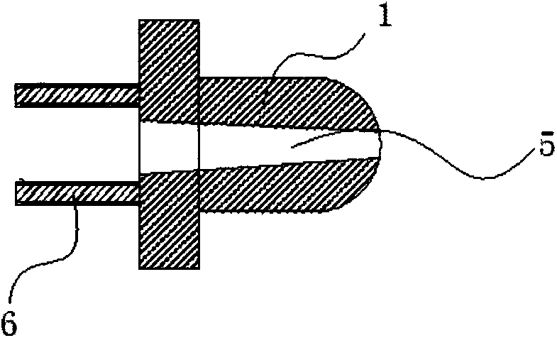
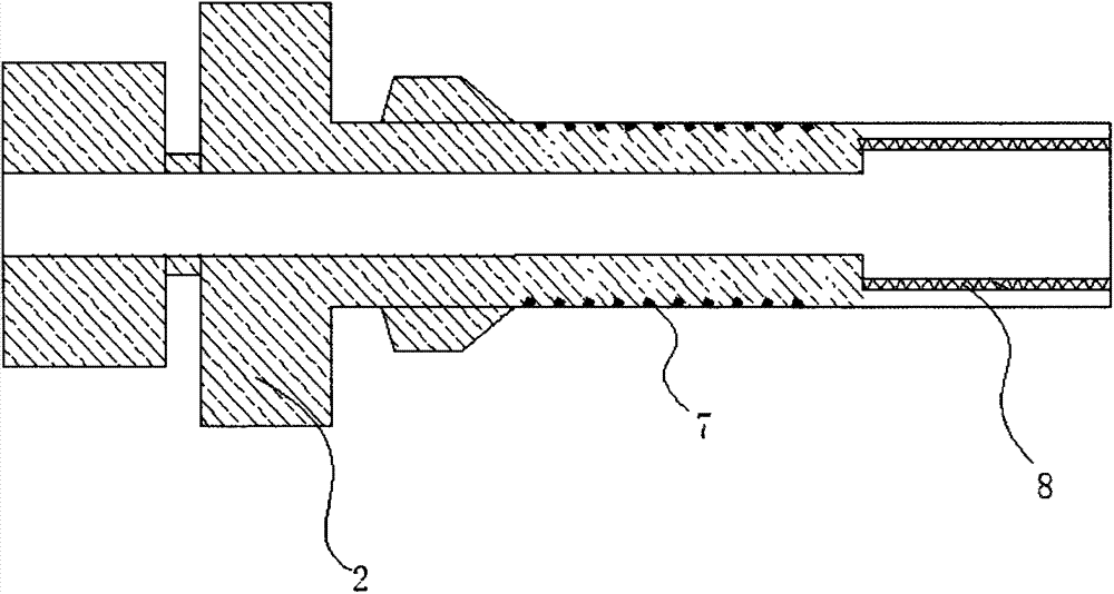
[0016] refer to Figure 1~3 As shown, the nozzle of the injection molding machine includes: a primary nozzle 1, a secondary nozzle 2, the primary nozzle 1 and the secondary nozzle 2 are provided with flow channels and communicated, the primary The nozzle 1 is provided with a first connecting end 6, the secondary nozzle is provided with a second connecting end 8, the primary nozzle 1 is connected to the secondary nozzle 2, and the primary nozzle 1 is connected to the secondary nozzle 2. The connecting portion of the secondary nozzle 2 is provided with a filter 3 , and the secondary nozzle 2 is equipped with a spiral heating wire 4 .

[0017] Preferably, a spiral groove 7 ...


PUM


Abstract

The invention discloses a nozzle for an injection molding machine and relates to the field of injection molding machines. The nozzle for the injection molding machine comprises a primary nozzle and a secondary nozzle; both the primary nozzle and the second nozzle are provided with runners and are communicated with each other; the primary nozzle is provided with a first connection end; the secondary nozzle is provided with a second connection end; the primary nozzle is connected with the secondary nozzle; the joint position of the primary nozzle and the secondary nozzle is provided with a filter screen; and the secondary nozzle is provided with a spiral heating wire. According to the nozzle for the injection molding machine, arrangement of the heating wire enables the nozzle for the injection molding machine to be difficult to block; and by arrangement of the filter screen, impurities in raw materials can be effectively filtered, the nozzle is prevented from being blocked, and in case of blockage, blockage can be cleared away after the primary nozzle is disassembled.

Description

technical field [0001] The invention relates to the field of injection molding machines, in particular to a nozzle of an injection molding machine. Background technique [0002] The nozzle of the injection molding machine is an important connecting part for the injection molding machine to complete the injection molding of the mold. Ordinary nozzles mostly have a one-stage structure and the nozzle itself does not have a heating function, but the heat will always be lost during the process of the raw material flow into the mold. Therefore, after the product is formed, it is easy to produce defects such as cold material marks and white spots. Moreover, the raw materials in the current plastic production are usually a mixture of several raw materials, but the melting points of various raw materials are different, and it is easy to block the nozzle during the continuous temperature change. The trouble is, after clogging, the entire nozzle needs to be unscrewed from the injecti...

Claims


Application Information

Patent Timeline
IPC IPC(8): B29C45/20
CPCB29C45/22B29C45/74
Inventor 徐国华
Owner SUZHOU CHANGFA PLASTICS
Why Eureka
Eureka Blog
Learn More