
Composite slag remover and manufacturing process thereof

A composite material and manufacturing process technology, applied in the direction of settlement tanks, etc., to achieve the effect of overcoming fragility, precise installation geometric dimensions, and improving strength

Active Publication Date: 2015-03-25
ZIBO BEICHEN CERAMICS EQUIP
View PDF1 Cites 0 Cited by
  • Summary
  • Abstract
  • Description
  • Claims
  • Application Information

AI Technical Summary

Problems solved by technology

Effectively improves the strength of the ceramic inner tank, overcomes the fragility of the ceramic material, and is easy to install, without the need to install a protective shell on the outside of the inner tank

Method used


Image

  • Composite slag remover and manufacturing process thereof
  • Composite slag remover and manufacturing process thereof
  • Composite slag remover and manufacturing process thereof

Examples


Embodiment Construction

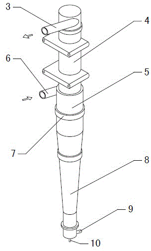
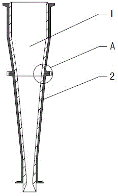
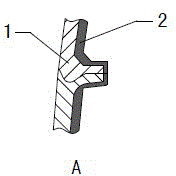
[0041] Figure 1~5 It is the best embodiment of the composite material slag remover and its manufacturing process of the present invention, below in conjunction with the attached Figure 1~6 The present invention will be further described.

[0042] Refer to attached figure 1 : Composite material slag remover, from top to bottom includes a cylindrical main body 4, a slurry feed head 5 and a cone-shaped cone 8 with a large upper part and a smaller lower part. The upper end of the main body 4 is provided with an end cover. A good pulp outlet 3 is provided in the direction, and a pulp inlet 6 is arranged tangentially on the pulp inlet head 5. The pulp inlet 6 and the good pulp outlet 3 are respectively located on both sides. The lower end of the cone 8 is provided with a horizontal slag outlet 9, and the bottom is provided There is a vertical flush port 10.

[0043] refer to Figure 2~3 , the main body 4, the pulp feeding head 5 and the cone 8 all have an isostatically pressed a...


PUM

PropertyMeasurementUnit
thicknessaaaaaaaaaa
particle sizeaaaaaaaaaa

Abstract

The invention provides a composite slag remover and a manufacturing process thereof, and belongs to the field of pulp slag removal equipment. The composite slag remover comprises an inner container (1) made of ceramic. The composite slag remover is characterized in that a layer of high molecular elastic material (2) coats the outer side of the inner container (1), and the inner container (1) and the high molecular elastic material (2) are composited into an integrated structure. The manufacturing process of the composite slag remover sequentially includes the steps that a green body, made of aluminum oxide, of the inner container (1) is prepared in an isostatic pressing mode under the pressure of 120-300Mpa, a numerically controlled lathe is utilized to turn the inner side and the outer side of the green body of the inner container (1), the green body is fired into the inner container (1), the molten high molecular elastic material (2) coats the outer side of the inner container (1) under the pressure of 20-30Mpa, and vulcanization is conducted. The composite slag remover has the advantages of being high in strength, light in weight, accurate in installing geometric dimension, convenient to install, low in using cost and friction coefficients of the ceramic inner container, and capable of improving the paper pulp purifying rate and achieving energy saving and environment friendliness.

Description

technical field [0001] A composite material slag remover and a manufacturing process thereof belong to the field of slurry slag removal equipment, and specifically relate to a composite material slag remover with a ceramic liner and a process for manufacturing the composite material slag remover. Background technique [0002] At present, the slag remover is widely used in the fields of papermaking and chemical industry. The slurry forms a high-speed swirling flow on the inner wall of the slag remover, and the impurities in the slurry cause great wear to the inner wall of the slag remover. The upper part of the slag remover uses plastic, and the lower part uses ceramics. The plastic on the upper part of the slag remover is easily worn and has a short service life. Chinese patent 201220738296.3 discloses a cone inner core of a high-concentration slag remover. The inner core is made of ceramic materials. The friction of the ceramic material is small, which improves the recyclin...

Claims


Application Information

Patent Timeline
Patent Type & Authority Patents(China)
IPC IPC(8): B01D21/02
Inventor 王世宝
Owner ZIBO BEICHEN CERAMICS EQUIP
Learn More