non-contact tonometer
A non-contact, tonometer technology, applied to tonometers and other directions, can solve the problems of high cost and difficult installation of solenoid valves, and achieve the effect of compact equipment
- Summary
- Abstract
- Description
- Claims
- Application Information
AI Technical Summary
Problems solved by technology
Method used
Image

Examples
no. 1 example
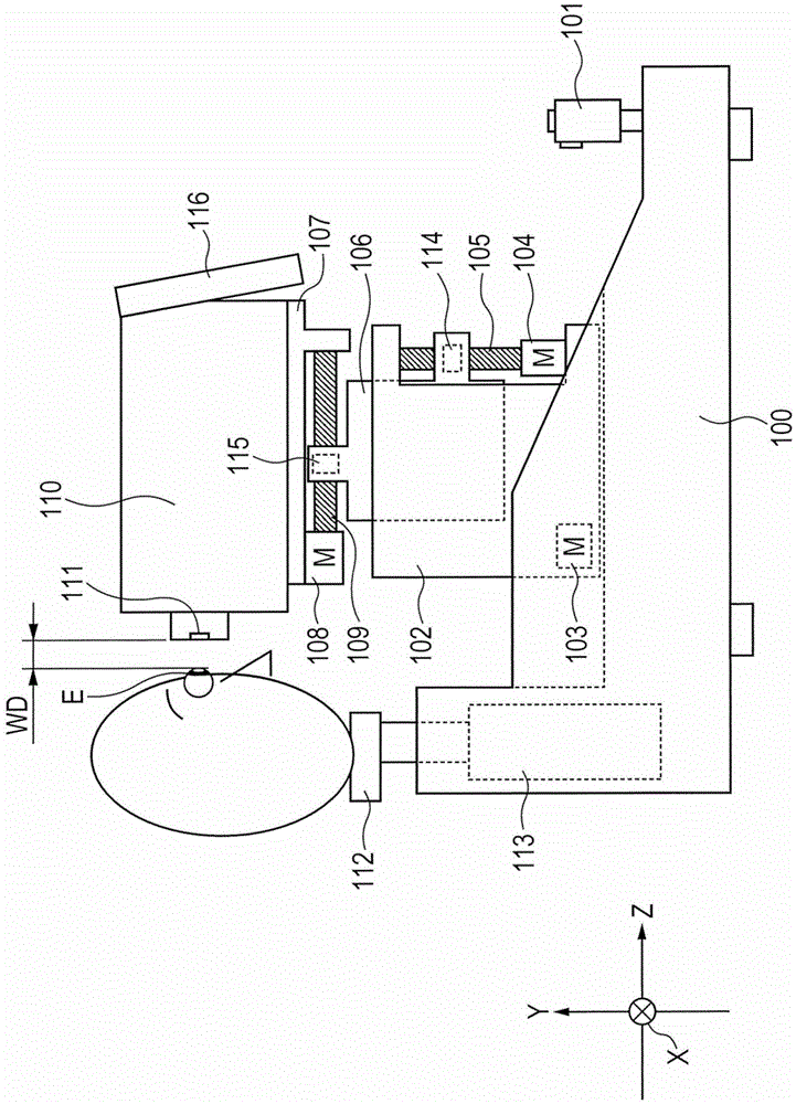
[0030] figure 1 is a diagram showing a schematic configuration of a non-contact tonometer according to the present invention.
[0031] The frame 102 is movable in a horizontal direction (hereinafter referred to as an X-axis direction) relative to the base 100 . The drive mechanism on the X-axis direction includes an X-axis motor 103 fixed on the base 100, a feed screw (not shown) that is connected to the output shaft of the motor, and is fixed in a manner that can move along the X-axis direction on the feed screw. Nut to box 102 (not shown). The motor 103 rotates to move the frame 102 in the X-axis direction by feeding the screw and the nut.
[0032] The frame 106 is movable in a vertical direction (hereinafter referred to as Y-axis direction) relative to the frame 102 . The driving mechanism on the Y-axis direction includes a Y-axis motor 104 fixed on the frame 102, a feed screw 105 connected to the output shaft of the motor, and a motor that is fixed on the frame 106 in a...
no. 2 example
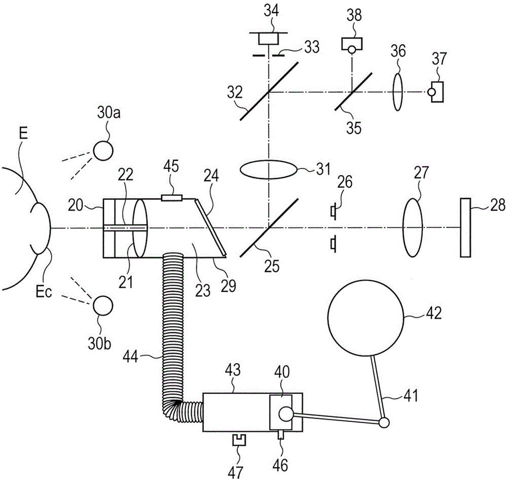
[0091] Usually, in a structure that determines the movement start position of the piston 40 as in the case of conventional products, in order to shorten the air injection time for the eye to be inspected, a hole for air discharge is formed near the middle of the cylinder 43 .
[0092] Since the air in the cylinder 43 is not compressed until the piston 40 passes through the hole, the piston 40 increases its drive speed without any air resistance and starts to compress the air while passing through the hole. Assume that the piston 40 is driven by the same force. In this case, if the initial velocity at the start time of air compression is high, the velocity of air jetted against the subject's eye is correspondingly high. This shortens the time to reach the pressure required for the measurement. The configuration according to the first embodiment has disadvantages in that a hole cannot be formed in the cylinder and an initial velocity of the piston 40 at the start of air compres...
PUM
 Abstract
Description
Claims
Application Information
 - R&D
- Intellectual Property
- Life Sciences
- Materials
- Tech Scout
- Unparalleled Data Quality
- Higher Quality Content
- 60% Fewer Hallucinations
Browse by: Latest US Patents, China's latest patents, Technical Efficacy Thesaurus, Application Domain, Technology Topic, Popular Technical Reports.
© 2025 PatSnap. All rights reserved.Legal|Privacy policy|Modern Slavery Act Transparency Statement|Sitemap|About US| Contact US: help@patsnap.com