Connecting device for rotors and indexing monitoring equipment for machining wheel grooves of rotors of steam turbines

A technology for steam turbine rotors and monitoring equipment, which is applied in metal processing equipment, metal processing mechanical parts, manufacturing tools, etc. Effect

Active Publication Date: 2013-12-25
HARBIN TURBINE
View PDF6 Cites 0 Cited by
  • Summary
  • Abstract
  • Description
  • Claims
  • Application Information

AI Technical Summary

Problems solved by technology

[0003] In order to solve the problems of time-consuming and labor-intensive use and high cost in the use of the existing indexing plate, the present invention further provides a connection device between the indexing monitoring equipment and the rotor for machining the wheel groove of the steam turbine rotor

Method used


Image

  • Connecting device for rotors and indexing monitoring equipment for machining wheel grooves of rotors of steam turbines
  • Connecting device for rotors and indexing monitoring equipment for machining wheel grooves of rotors of steam turbines

Examples


specific Embodiment approach 1

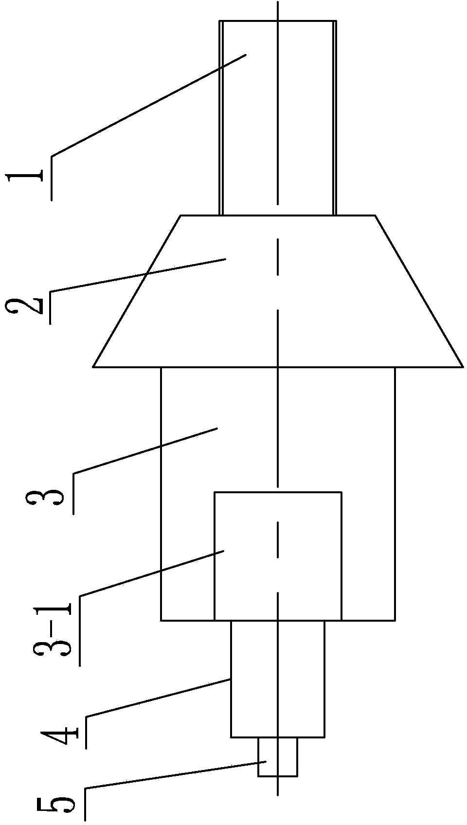
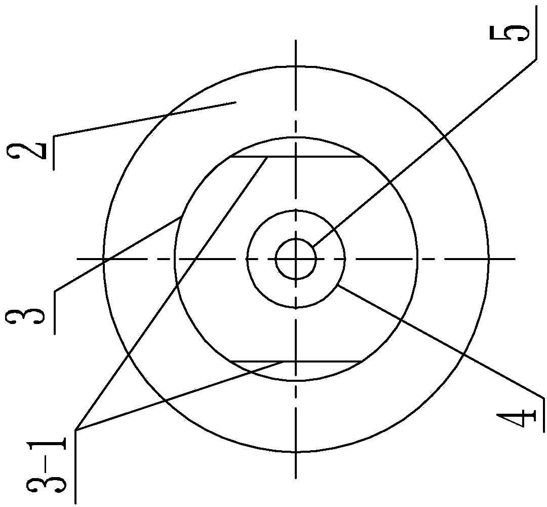
[0009] Specific implementation mode one: as Figure 1~2 As shown, the connection device between the indexing monitoring equipment for machining the wheel groove of the steam turbine rotor and the rotor in this embodiment includes a first cylindrical section 1, a circular platform section 2, a second cylindrical section 3, a fourth cylindrical section 4 and a fifth cylindrical section 5 , the first cylindrical section 1, the circular frustum section 2, the second cylindrical section 3, the fourth cylindrical section 4 and the fifth cylindrical section 5 are fixed together in sequence along the axial direction, one end of the first cylindrical section 1 and the small One end of the second cylindrical section 3 is affixed to the large end of the round table section 2, the first cylindrical section 1 is processed with external threads along the length direction, and the second cylindrical section 3 is symmetrically processed with two rectangular platforms 3- 1.

[0010] The exter...

specific Embodiment approach 2

[0011] Specific implementation mode two: as figure 1 As shown, the rectangular platform 3 - 1 of this embodiment is located on the side close to the fourth cylinder segment 4 . With such a design, the first cylindrical section 1 can be fastened to the top hole of the rotor with a wrench. Other components and connections are the same as those in the first embodiment.

specific Embodiment approach 3

[0012] Specific implementation mode three: as figure 1 As shown, the outer diameters of the second cylindrical section 3 , the fourth cylindrical section 4 and the fifth cylindrical section 5 in this embodiment are set from large to small. In such a design, the fifth cylindrical section 5 is used for positioning with the pin hole of the indexing monitoring equipment, the fourth cylindrical section 4 is fixedly connected with the indexing monitoring equipment through the jackscrew, and the second cylindrical section 3 can realize the first cylindrical section 3 through a wrench. The segment is fastened to the rotor. Other compositions and connections are the same as those in Embodiment 1 or 2.


PUM


Abstract

The invention discloses a connecting device for rotors and indexing monitoring equipment for machining wheel grooves of the rotors of steam turbines, and relates to a connecting device. The connecting device is used for solving problems of long time consumption and high labor consumption and service cost of an existing indexing disc during usage. The connecting device comprises a first cylinder section (1), a circular truncated cone section (2), a second cylinder section (3), a fourth cylinder section (4) and a fifth cylinder section (5) which are axially, sequentially and fixedly integrated. One end of the first cylinder section (1) is fixedly connected with a small end of the circular truncated cone section (2), one end of the second cylinder section (3) is fixedly connected with a large end of the circular truncated cone section (2), external threads are machined on the first cylinder section (1) along the length direction of the first cylinder section (1), and two rectangular platforms (3-1) are symmetrically machined on the second cylinder section (3). The connecting device is used for connecting the rotors with the indexing monitoring equipment for machining the wheel grooves of the rotors of the steam turbines.

Description

technical field [0001] The invention relates to a connection device, in particular to a connection device between an indexing monitoring device for machining a wheel groove of a steam turbine rotor and a rotor. Background technique [0002] In the process of rotor wheel groove processing, in order to ensure the accuracy of rotor indexing and avoid major quality accidents caused by indexing errors, it is necessary to install an indexing monitoring device on the rotor adjustment end side to ensure the accuracy of rotor indexing. accuracy. The existing connection indexing plate positioned by the inner and outer spigots of the rotor, the connection indexing plate is processed and used to customize different tooling connection plates according to the size of different products, which is time-consuming and labor-intensive during use. The input of use cost. Contents of the invention [0003] In order to solve the problems of time-consuming and labor-intensive use and high cost ...

Claims


Application Information

Patent Timeline
Patent Type & Authority Applications(China)
IPC IPC(8): B23Q11/00
Inventor 李保树曹滨滨马静莉张丽艳柳薇
Owner HARBIN TURBINE
Why Eureka
Try Eureka