
Apparatus and method for detecting contact

A technology of touch sensing and touch input, applied in the field of single-layer structure touch sensing devices, which can solve the problems of thick touch screen panel, double image, and difficult to determine

Inactive Publication Date: 2013-12-18
MELFAS
View PDF3 Cites 8 Cited by
  • Summary
  • Abstract
  • Description
  • Claims
  • Application Information

AI Technical Summary

Problems solved by technology

[0009] However, the judgment of the positions of the two X coordinates and the Y coordinates, due to the ghosting phenomenon, which combination of the two X coordinates and the Y coordinates is the real position of the two contact points is difficult to determine
[0010] For example, due to ghosting, etc., the user touches the third position of the X axis and the third position of the Y axis (X3, Y3) and the sixth position of the X axis and the fifth position of the Y axis (X6, Y5). point, but it may be misidentified as the sixth position of the X axis and the third position of the Y axis (X6, Y3) and the third position of the X axis and the fifth position of the Y axis (X3, Y5). point
[0011] As a method to solve the ghost phenomenon, there is a combination of XN electrodes and YM electrodes, for example, driving (exciting) each X electrode in sequence, at this time, a mutual capacitance of a two-layer structure that senses signal changes from each Y electrode can be adopted (mutual-capacitance) method, but the mutual electrostatic capacitance (2-Layer mutual-capacitance) method of the two-layer structure will make the thickness of the touch screen panel thicker

Method used


Image

  • Apparatus and method for detecting contact
  • Apparatus and method for detecting contact
  • Apparatus and method for detecting contact

Examples


Embodiment Construction

[0030] Embodiments of the present invention will be described in detail below with reference to the drawings and contents described in the drawings, but the present invention is not limited or limited to the embodiments.

[0031] On the other hand, in describing the present invention, when it is considered that a detailed description of a related known function or structure will unnecessarily obscure the gist of the present invention, the detailed description will be omitted. In addition, the terminology used in the present invention is a term for appropriately expressing the embodiments of the present invention, and may differ depending on the intention of a user, an operator, or the practice in the field to which the present invention pertains. Therefore, the definitions of terms shall be based on the contents throughout the specification.

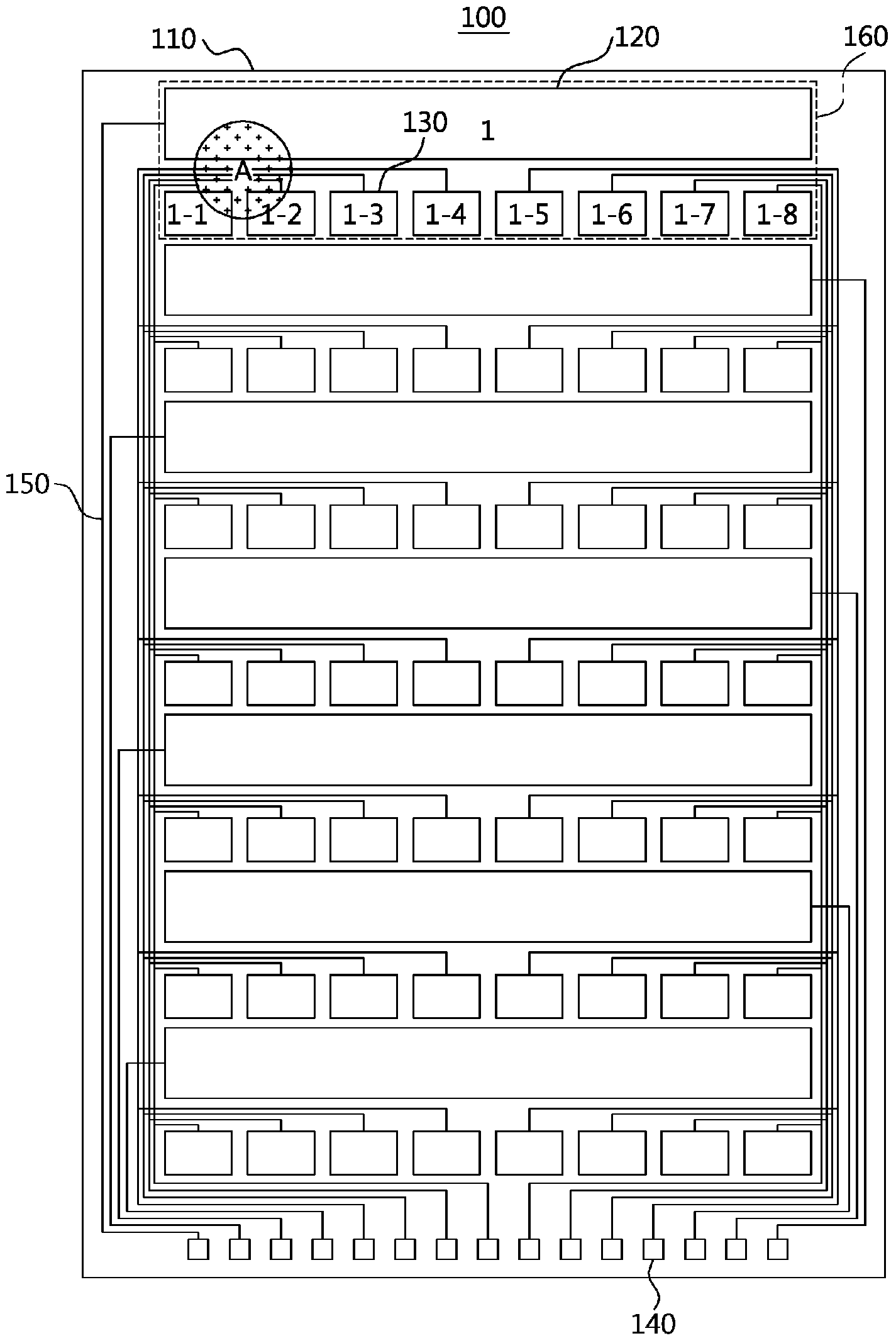
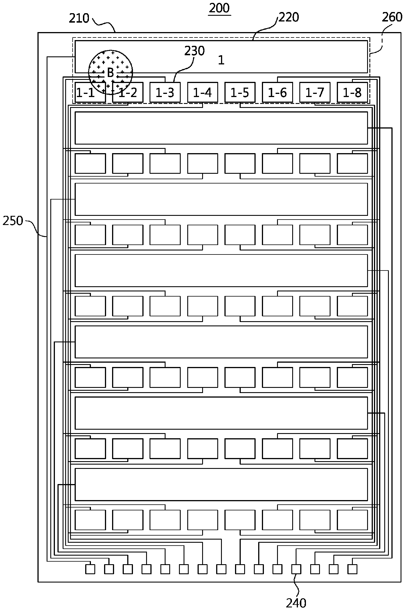
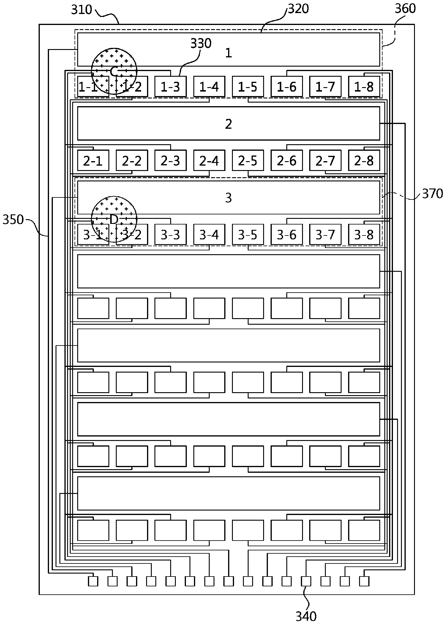
[0032] figure 1 is a diagram showing the structure of a touch sensing device according to an embodiment of the present invention.

[...


PUM


Abstract

An apparatus for detecting contact, according to the present invention, comprises: a substrate; a plurality of first electrodes which are formed on the substrate; a plurality of second electrodes which are formed on the substrate; and a controller chip for receiving applied signals from the plurality of first electrodes and the plurality of second electrodes, and determining a contact input, wherein the controller chip eliminates a value of a predetermined proportion of values from each of the signals.

Description

technical field [0001] The present invention relates to a touch sensing device and method, more particularly, to a single-layer (Single-Layer) structure touch sensing device and method, which can determine more than one touch input acquired in sequence. Background technique [0002] Mobile phones equipped with touch screens are widespread, and with the popularization of various types of smartphones, research on touch-sensing technology has become increasingly active. [0003] A typical touch sensing device is a touch panel, which can be divided into resistive film, electrostatic capacitance, ultrasonic, infrared, etc. according to its operation method. Among them, the advantages of the electrostatic capacitance method are that it has excellent durability and life and supports multi-touch functions. Recently, Its field of application is expanding. [0004] Capacitive touch screens can be divided into the following methods, that is, using the self-capacitance (Self-Capacitanc...

Claims


Application Information

Patent Timeline
Patent Type & Authority Applications(China)
IPC IPC(8): G06F3/041
CPCG06F3/04164G06F3/04182G06F3/0443G06F3/0418G06F2203/04104
Inventor 金才弘
Owner MELFAS
Learn More