
Water leakage detection mechanism

A detection mechanism, water body technology, applied in the direction of detecting the appearance of fluid at the leak point, using liquid/vacuum degree for liquid tightness measurement, etc., can solve the problems of excessively sensitive water pump seal failure, leakage, slowness, etc., to achieve the control method Variety, accurate conclusions, and good applicability

Active Publication Date: 2013-12-18
INTEX IND (XIAMEN) CO LTD
View PDF7 Cites 8 Cited by
  • Summary
  • Abstract
  • Description
  • Claims
  • Application Information

AI Technical Summary

Problems solved by technology

However, considering the instability of this water leakage situation, common detection measures will produce two extremes, that is, too sensitive and prematurely judge the failure of the water pump seal, or be too slow to give a warning when the leakage is serious

Method used


Image

  • Water leakage detection mechanism
  • Water leakage detection mechanism
  • Water leakage detection mechanism

Examples


Embodiment 1

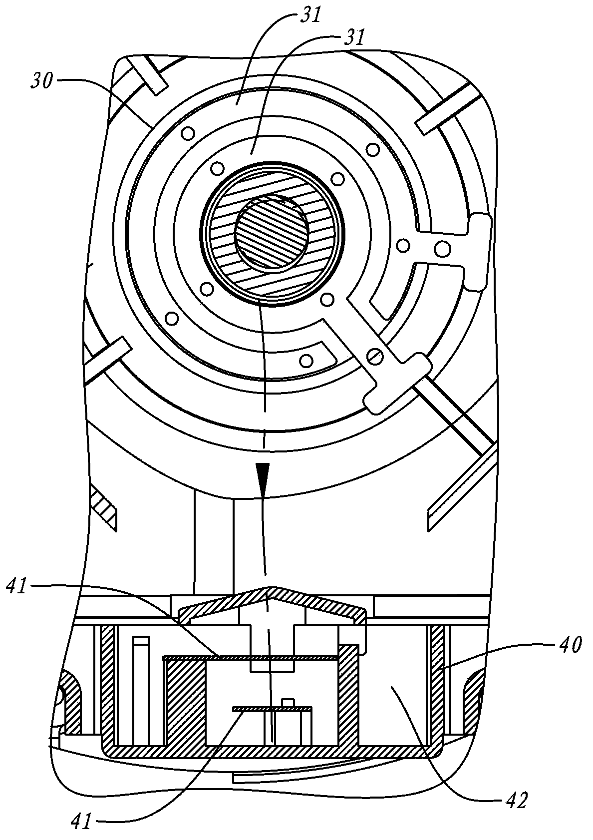
[0044] Such as Figure 1 to Figure 5 As shown, several schematic diagrams of Embodiment 1 of the water leakage detection mechanism of the present invention.

[0045] combine Figure 1 to Figure 3 , The present embodiment is a centrifugal water pump for a SPA pool. The drive shaft 11 of the pump body 20 is placed horizontally, so the drive component 10 (a motor in this example) and the pump body 20 are arranged in left and right rows. A frequency measuring probe 30 is fixed on the outer wall of the pump body 20 of the centrifugal water pump, the center of the bottom of the pump seat 21, that is, around the pump body 20 where the power shaft 11 of the water pump cooperates with the pump body 20, the frequency measuring probe has an exposed The water-touching surface is provided with a frequency-side electrode 31, and the frequency-measuring electrode 31 uses two conductive electrodes to detect water leakage. The position where the frequency measuring probe 30 is located is a ...

Embodiment 2

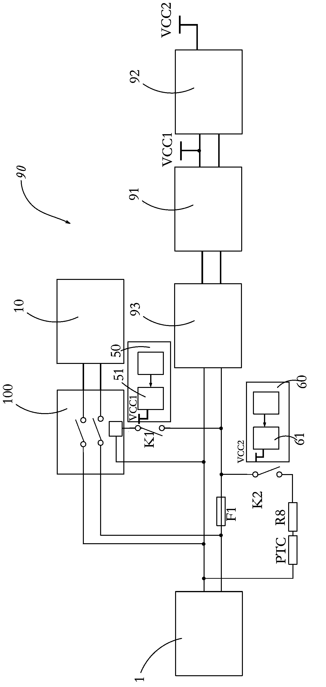
[0054] Such as Figure 6 Shown is a schematic diagram of Embodiment 2 of the present invention. The final driving part 10 of this embodiment is an AC motor, and the structure of the pump body 20 is the same as that of the first embodiment. The difference is in the control module 90 part. The control module 90 also includes a frequency test relay 51 and a single test relay 61, a power supply 1, a rectifier circuit 93, a first voltage stabilizing block 91 and a second voltage stabilizing block 92; this embodiment also includes a leakage protector 2 connected in series In the current loop of the entire control module 90 and the current loop (not marked) of the driving component 10; wherein, the on-off loop K1 of the frequency test relay 51 is connected in parallel with the on-off loop K2 of the single test relay 61, and is connected in parallel to the Between one AC input terminal of the leakage protector 2 and another AC output terminal of a different line—this scheme utilizes...


PUM


Abstract

The invention discloses a water leakage detection mechanism. The water leakage detection mechanism is characterized by comprising a frequency detection probe and a single-detection probe. The frequency detection probe is fixed to a matching position of a power shaft of a water pump and a pump body and provided with an exposed water contact surface, and a frequency detection electrode is arranged on the water contact surface; the single-detection probe is fixed below the matching position of the power shaft of the water pump and the pump body and in a water dropping track and provided with a water containing box with an upward opening, and the water containing box is provided with a water containing space for collecting dropping and leaking water; a single-detection electrode used for detecting leaking water in an electric conduction method is arranged in the water containing space; the frequency detection electrode is connected with a frequency detection module; the single-detection electrode is connected with a single-detection module; both the frequency detection module and the single-detection module are located in a control module which can control a driving component where the power shaft is located. According to the water leakage detection mechanism, water leakage detection conclusions of the water pump can be more accurate and reliable due to the combination of the single-detection module and the frequency detection module; water leakage conditions of the centrifugal water pump can be accurately detected and the water leakage detection conclusions are accurate and reliable because the single-detection electrode and the frequency detection electrode are matched with the single-detection module and the frequency detection module which are suitable for the single-detection electrode and the frequency detection electrode.

Description

technical field [0001] The invention relates to a water leakage detection mechanism, in particular to a water leakage detection device for the shaft sealing part of a centrifugal water pump. Background technique [0002] Centrifugal water pumps are widely used in water fields, such as irrigation, industry, water sports, etc. Its structure is relatively mature, usually a spiral pump body with an involute profile, and the coaxial pump blades inside are driven to rotate, sucking in the water body axially and discharging it circumferentially, so as to realize the rapid movement of the water body. It can be seen from its structure that the pump blades are fixed shafts fitted in the pump body, and the pumped water body is resident in the space between the pump blades and the pump body, and the pump blades need to be driven by rotating power from the outside of the pump body. Commonly used driving components such as Electric motors, internal combustion engines, etc. In this way, ...

Claims


Application Information

Patent Timeline
IPC IPC(8): G01M3/16
Inventor 林华乡许耀元
Owner INTEX IND (XIAMEN) CO LTD
Learn More